=================================
=================================
=================================
OpenGL을 쓰고 항시 API를 쓰고 다시 해제해주어야 하는 API들은 해제 해주는것을 잊지 마세요
예로들어 wglMakeCurrent(...)로 들자면
HDC hdc = getHDC();

HGLRC hglrc = getHGLRCRES_GL();

::wglMakeCurrent(hdc, hglrc); //사용

//--------------------------------------
//{랜더링 코드들

..................................................................

//}
//--------------------------------------

::wglMakeCurrent(NULL, NULL); //::wglMakeCurrent(hdc, NULL);  //해제
위와같이 wglMakeCurrent(...) 랜더링 부분에 Api 사용과 해제 부분을 제대로 하지 않으면 다른
위치의 wglMakeCurrent(...) 를 사용시 문제가 생길수 있습니다.
=================================
=================================
=================================
출처: http://soen.kr/lecture/library/opengl/opengl-10.htm
10.텍스처
10-1.비트맵
OpenGL은 3차원 그래픽 라이브러리이지만 2차원의 그래픽을 관리하는 기능도 제공한다. 텍스처 맵핑을 위해 2차원 비트맵을 처리하는 기능이 필요하며 또한 3차원 그래픽이라도 투영 후에는 2차원이 되므로 이 또한 다룰 수 있어야 하기 때문이다. 물론 전문적인 2차원 그래픽 라이브러리에 비할 바는 아니다.
비트맵은 미리 만들어진 이미지를 의미하며 다양한 크기와 색상을 가질 수 있다. 그러나 OpenGL에서는 흑백 이미지만을 비트맵이라고 칭하며 컬러 이미지는 픽셀맵(Pixelmap)이라는 별도의 용어를 사용한다. bit가 용어가 원래 0과 1만을 의미하는 흑백적인 뜻이기 때문이라고 한다. 사실 디지털 이미지라는 정의가 가장 정확한데 어쨌든 OpenGL은 컬러 이미지와 흑백 이미지를 구분한다고 알아 두자.
비트맵은 보통 대용량의 래스터 데이터로 구성되므로 파일 형태로 저장되는 것이 일반적이다. 그러나 안타깝게도 OpenGL은 파일 입출력 기능을 제공하지 않으므로 파일이나 리소스로부터 비트맵을 생성하기 어렵다. 간단한 이미지라면 메모리에서 래스터 데이터를 직접 정의하여 만들어 써야 한다. 모눈 종이에 다음과 같이 이미지를 디자인해 보자.

비트맵을 만드는 아주 원시적인 방법인데 각 칸의 흰색은 이진수 0에 대응시키고 검정색은 1에 대응시킨다. 이 수를 나열하면 2진수가 나오는데 자리 수가 너무 많으므로 보통 16진수로 압축한다. 이렇게 만든 16진수를 배열에 순서대로 기록하면 비트맵이 된다. OpenGL의 비트맵은 아래에서 위로 정의되므로 제일 아래줄부터 배열에 기록한다.
비트맵의 래스터 데이터는 처리의 효율성을 위해 4바이트 단위로 정렬된다. 왜냐하면 대부분의 컴퓨터는 32비트이고 한번에 4바이트씩 읽고 쓰는 속도가 가장 빠르기 때문이다. 한 행이 4의 배수가 안되더라도 뒷 부분에 더미를 추가해서라도 4의 배수로 맞추는 것이 유리하다. 그러나 위 이미지는 한 행이 2바이트 밖에 안되어 더미를 넣으면 무려 2배나 커진다. 정렬 단위를 바꾸고 싶다면 다음 함수로 비트맵의 저장 방식을 변경해야 한다.
void glPixelStore[f, i](GLenum pname, GLfloat param);
이 함수로 바이트 순서(GL_PACK_SWAP_BYTES)나 바이트 정렬(GL_PACK_ALIGNMENT) 등의 옵션을 지정한다. 메모리에서 비트맵을 읽을 때의 정렬은 GL_UNPACK_ALIGNMENT 옵션으로 지정하며 이 값의 디폴트가 4이므로 4바이트 정렬된다. 2나 1로 바꾸면 더 작은 단위로 정렬할 수 있되 단, 값을 일일이 잘라서 읽어야 하므로 속도에는 불리하다. 비트맵의 출력 위치는 다음 함수로 지정한다.
void glRasterPos[2,3,4][s,i,f,d][v](x, y,z,w);
좌표를 지정하는 함수이므로 glVertex 함수와 형식이 거의 동일하다. 이 함수가 지정한 좌표가 현재 위치가 되며 이 위치에서부터 비트맵이 출력되고 비트맵 출력 후 현재 위치는 자동으로 다음 위치로 갱신된다. 마치 텍스트 모드에서 다음 문자가 출력될 위치를 지정하는 커서의 개념과 유사하다.
이 함수가 지정한 좌표는 변환의 영향을 받는다. 만약 변환에 상관없이 윈도우의 특정 좌표에 출력하려면 glWindowPos 함수를 대신 사용한다. 그러나 이 함수는 OpenGL 1.4 이후부터만 지원되므로 윈도우즈의 기본 구현에서는 당장 사용할 수 없다. 비트맵을 출력할 때는 다음 함수를 호출한다.
void glBitmap(GLsizei width, GLsizei height, GLfloat xorig, GLfloat yorig, GLfloat xmove, GLfloat ymove, const GLubyte * bitmap);
제일 마지막 인수인 bitmap이 비트맵의 모양을 정의하는 래스터 데이터 배열이다. width, height는 비트맵의 폭과 높이를 픽셀 단위로 알려 주는데 일차원 배열의 래스터만으로는 비트맵의 모양을 알 수 없기 때문에 크기 정보를 별도로 제공해야 한다. 위 비트맵은 16 * 16 크기이므로 폭과 높이가 모두 16이다.
xorig, yorig 인수는 비트맵의 어느 부분이 현재 위치에 출력될 것인지 원점을 지정한다. 보통은 좌하단인 (0,0)을 지정하여 비트맵의 아래쪽이 현재 위치에 출력되지만 모양이 특이한 비트맵은 원점을 변경할 수도 있다. xmove, ymove는 비트맵을 그린 후에 이동할 양을 거리를 지정한다. 마치 문자를 출력한 후 커서를 옮기듯이 현재 위치를 적당량 띄운다.
비트맵은 단 두 가지 색으로만 구성된 그림이지만 그렇다고 해서 꼭 흑백으로만 출력해야 하는 것은 아니다. glColor 함수로 색상을 지정하면 비트맵의 1에 대응되는 부분에 이 색상이 출력된다. 그래서 단색 비트맵이지만 노란색이나 빨간색으로도 출력할 수 있다. 다음 예제는 앞에서 디자인한 16 * 16 크기의 비트맵을 출력한다.
| Bitmap |
void DoDisplay() {
    static GLubyte bitmap[] = {
        0x07,
        0xe0,
        0x18,
        0x18,
        0x20,
        0x04,
        0x43,
        0xc2,
        0x44,
        0x22,
        0x88,
        0x11,
        0x81,
        0x81,
        0x81,
        0x81,
        0x80,
        0x01,
        0x80,
        0x01,
        0x92,
        0x49,
        0x4c,
        0x32,
        0x40,
        0x02,
        0x20,
        0x04,
        0x18,
        0x18,
        0x07,
        0xe0
    };
    glClear(GL_COLOR_BUFFER_BIT);
    glPixelStorei(GL_UNPACK_ALIGNMENT, 2);
    glColor3f(1, 1, 0);
    glRasterPos2f(0.5, 0.5);
    glBitmap(16, 16, 0, 0, 20, 0, bitmap);
    glBitmap(16, 16, 0, 0, 20, 0, bitmap);
    glBitmap(16, 16, 0, 10, 20, 0, bitmap);
    glFlush();
}
bitmap 배열에 래스터 데이터를 16진수로 저장했다. 2바이트 정렬로 지정했으므로 별도의 더미 데이터를 삽입할 필요는 없으며 아래행부터 순서대로 죽 나열하면 된다. 만약 4바이트 정렬이라면 한 행당 최소 4바이트를 써야 하므로 두 바이트마다 0x00, 0x00을 삽입해야 한다.
색상은 노란색으로 지정했다. 비트맵의 색상은 glBitmap을 호출할 때 적용되는 것이 아니라 glRasterPos를 호출할 때 결정되므로 glRasterPos 함수를 호출하기 전에 먼저 지정해야 한다. 두 함수의 순서를 바꾸면 디폴트인 흰색으로 출력된다. 출력 위치는 0.5, 0.5로 지정했으므로 오른쪽 위 중간쯤에에서부터 비트맵이 나타날 것이다.

세 개의 비트맵을 출력해 보았다. xmove를 모두 20으로 지정했으므로 비트맵 하나를 출력한 후 오른쪽으로 20픽셀만큼 이동한다. 비트맵 폭인 16보다 4만큼 더 주어 약간씩 여백을 띄웠다. 만약 ymove를 20으로 지정하면 비트맵은 세로로 연이어 출력될 것이다. xmove, ymove는 비트맵을 연속 출력할 때 방향과 거리를 지정하는 인수이다.
앞쪽 두 비트맵은 원점을 (0,0)으로 지정하여 비트맵의 좌하단이 현재 위치에 대응된다. 세번째 비트맵은 y 원점을 10으로 주어 비트맵의 위쪽 10픽셀 지점이 현재 위치에 출력되며 그래서 비트맵이 조금 아래쪽으로 내려간다. 원점을 조정하는 기능은 폰트처럼 베이스가 각각 다른 이미지를 출력할 때 기준선에 맞추어 나란히 출력하기 위해서이다.
3차원 그래픽에서는 글꼴도 비트맵으로 제작하여 직접 출력하는 경우가 많은데 영문자의 경우 알파벳마다 베이스가 제각각이다. 이런 글꼴 비트맵은 모양에 따라 원점을 달리해야 한다. 한글은 정사각형 문자이므로 원점 조정을 따로 할 필요가 없고 글자의 폭도 대부분 균일하므로 띄어쓰는 간격도 일정하다. 세종대왕 만세.
10-2.픽셀맵
컬러를 표현할 수 있는 픽셀맵은 비트맵에 비해서는 이미지를 만들거나 출력하기 훨씬 더 복잡하다. 출력 함수는 다음과 같다.
void glDrawPixels(GLsizei width, GLsizei height, GLenum format, GLenum type, const GLvoid * data);
width, height는 이미지의 폭과 높이이다. format은 픽셀의 색상 구성이며 GL_RGB, GL_BGA 등을 지정한다. 이미지 파일에 따라 색상 정보가 RGB 순으로 되어 있는 것이 있고 BGA 순으로 되어 있는 것이 있다. 포맷의 종류는 레퍼런스를 참고하기 바란다. type은 data 배열의 요소 타입을 지정하며 data가 실제 이미지 정보인 래스터 데이터이다. 다음 예제는 간단한 픽셀맵을 배열로 정의하고 출력한다.
void DoDisplay() {
    GLubyte data[32 * 32*3];
    for(int y=0;y<32;y++) {
        for(int x=0;x<32;x++) {
            data[y * 32*3+x*3+0] = 0;
            data[y*32*3+x*3+1] = 0xff;
            data[y*32*3+x*3+2] = 0x00;
        }
    }
    glClear(GL_COLOR_BUFFER_BIT);
    glRasterPos2f(0.0, 0.0);
    glDrawPixels(32, 32, GL_RGB, GL_UNSIGNED_BYTE, data);
    glFlush();
}
32*32크기의 픽셀맵을 정의하되 각 픽셀당 색상 정보 3개씩이 필요하므로 총 필요한 바이트수는 32*32*3이다. 이렇게 준비된 버퍼안에 각 점에 대해 RGB 요소를 일일이 정의하면 작으나마 아이콘 크기 정도의 이미지를 만들 수 있다. 그러나 이 작업은 16진수 3072개를 일일이 쳐 넣어야 하므로 제정신을 가진 사람이 손으로 할만한 작업이 못된다. 이미지로부터 색상 정보를 16진수로 추출해 내는 것만 해도 보통 일이 아니다.
그래서 어쩔 수 없이 루프를 돌며 모든 픽셀에 대해 R, G 요소는 255로 대입하고 B 요소는 0으로 대입하여 노란색으로 채워 넣었다. 좀 비겁하지만 귀차니즘으로 인해 모든 픽셀이 노란색인 작은 사각형 이미지를 하나 만든 것이다. 이렇게 만든 이미지를 화면 중앙에 출력했다. 픽셀맵은 비트맵과는 달리 원점을 지정하는 기능이 없으므로 무조건 이미지의 좌하단이 현재 위치에 출력된다. 그래서 중앙에서 약간 오른쪽 위에 이미지가 출력되었다.

이 예제는 픽셀맵을 출력하는 가장 원론적인 방법을 보이기 위해 작성한 것 뿐이다. 제대로 모양을 갖춘 이미지를 사용하려면 파일에서 읽어오는 것이 원칙적이다. OpenGL은 이미지 파일을 읽는 기능을 제공하지 않으므로 운영체제별로 적당한 이미지 읽기 함수를 만들어 사용해야 한다. 이 강좌는 윈도우즈 환경에서 실습을 진행하고 있으므로 윈도우즈 API로 읽기 용이한 BMP 파일을 출력했다.
GLubyte * LoadBmp(const char * Path, int * Width, int * Height) {
        HANDLE hFile;
        DWORD FileSize,
        dwRead;
        BITMAPFILEHEADER * fh = NULL;
        BITMAPINFOHEADER * ih;
        BYTE * pRaster;
        hFile = CreateFileA(
            Path, GENERIC_READ, 0, NULL, OPEN_EXISTING, FILE_ATTRIBUTE_NORMAL, NULL
        );
        if (hFile == INVALID_HANDLE_VALUE) {
            return NULL;
        }
        FileSize = GetFileSize(hFile, NULL);
        fh = (BITMAPFILEHEADER *)malloc(FileSize);
        ReadFile(hFile, fh, FileSize, & dwRead, NULL);
        CloseHandle(hFile);
        int len = FileSize - fh -> bfOffBits;
        pRaster = (GLubyte *)malloc(len);
        memcpy(pRaster, (BYTE *)fh + fh -> bfOffBits, len);
        // RGB로 순서를 바꾼다.
        for (BYTE * p = pRaster; p < pRaster + len - 3; p += 3) {
            BYTE b = * p;
            *p = * (p + 2);
            *(p + 2) = b;
        }
        ih = (BITMAPINFOHEADER *)((PBYTE)fh + sizeof(BITMAPFILEHEADER));
        *Width = ih -> biWidth;
        *Height = ih -> biHeight;
        free(fh);
        return pRaster;
    }

    void DoDisplay() {
        GLubyte * data;
        int Width,
        Height;
        glClear(GL_COLOR_BUFFER_BIT);
        data = LoadBmp("chestnut.bmp", & Width, & Height);
        if (data != NULL) {
            glRasterPos2f(-0.5, -0.5);
            glDrawPixels(Width, Height, GL_RGB, GL_UNSIGNED_BYTE, data);
            free(data);
        }
        glFlush();
    }
이 예제의 LoadBmp 함수는 인수로 전달받은 이미지 파일로부터 래스터 데이터를 배열로 읽어들인다. BMP 파일의 구조와 파일 입출력 함수 정도만 쓸 수 있으면 이 정도 함수는 어렵지 않게 만들 수 있다. 파일에서 래스터 데이터에 해당하는 부분을 추출하여 버퍼에 복사하면 된다. 단, BMP는 색상 정보가 BGR 순으로 저장되어 있으므로 RGB 순서로 바꾸어 사용했다. OpenGL 도 BGR 순의 이미지 포맷인 GL_BGR을 지원하지만 안타깝게도 윈도우즈의 OpenGL은 버전이 낮은 관계로 GL_BGR을 지원하지 않는다.
LoadBmp 함수에 대한 자세한 분석이나 설명은 생략한다. 관심있는 사람은 Win32 관련 서적을 참고하기 바란다. 어떤 책이라고 굳이 꼭 집어서 소개하지는 않겠지만 시중에 좋은 Win32 서적들이 참 많이 있다. 이미지를 파일로 저장하는 기능이 필요하다면 SaveBmp 함수를 만들어 사용하면 된다. 만약 윈도우즈가 아닌 다른 운영체제에서 실습을 진행하거나 프로젝트를 해야 한다면 해당 운영체제의 이미지 조작 방법을 참고하거나 아니면 남이 만들어 놓은 유틸리티 함수를 구해 보도록 하자. 실행하면 컬러 이미지가 출력될 것이다.

이 예제에서 사용한 chestnut.bmp 파일은 잘 익은 밤 이미지이며 글쓴이가 손수 찍은 사진이다. 어떤 이미지든지 BMP로 변환해서 사용하면 위 함수를 활용할 수 있다. 안타깝게도 BMP는 윈도우즈 전용 포맷이라 다른 운영체제에서 사용하기는 어렵다. 좀 더 범용적인 포맷을 사용하되 압축 포맷보다는 TGA같은 비압축 포맷이 유리하다. JPG나 PNG 같은 압축 포맷도 별도의 그래픽 라이브러리를 활용하면 물론 사용할 수 있다.
파일로부터 이미지를 구하는 방법 외에 이미 출력된 화면의 이미지를 재사용할 수도 있다. 색상 버퍼의 픽셀값을 버퍼로 읽어들이거나 색상 버퍼의 일정 영역을 다른 곳으로 복사하면 된다. 다음 함수들은 화면의 일부를 버퍼로 읽어 들이고 화면끼리 복사한다. glRasterPos로 복사할 위치를 지정한 후 이 함수로 복사한다.
void glReadPixels(GLint x, GLint y, GLsizei width, GLsizei height, GLenum format, GLenum type, GLvoid * data);
void glCopyPixels(GLint x, GLint y, GLsizei width, GLsizei height, GLenum type);
복사할 영역과 복사할 정보의 종류를 밝힌다. type에 GL_COLOR를 지정하면 색상 데이터를 복사하는 것이고 GL_DEPTH나 GL_STENCIL을 지정하면 깊이 정보와 스텐실 정보까지 복사한다. 다음 예제는 밤 이미지의 일부를 왼쪽 아래로 복사한다.
void DoDisplay() {
    GLubyte *data;
    int Width, Height;
    glClear(GL_COLOR_BUFFER_BIT);
    data = LoadBmp("chestnut.bmp", &Width, &Height);
    if(data != NULL) {
        glRasterPos2f(-0.5, -0.5);
        glDrawPixels(Width, Height, GL_RGB, GL_UNSIGNED_BYTE, data);
        free(data);
    }
    glRasterPos2f(-1.0, -1.0);
    glCopyPixels(100, 100, 80, 50, GL_COLOR);
    glFlush();
}
실행 결과는 다음과 같다.

이미지끼리 복사해서 별 실용성이 없어 보이지만 3차원 그래픽으로 그린 이미지의 일부를 잘라 텍스처로 사용할 때는 이런 기법이 편리하다. 화면에 그려진 래스터 데이터를 활용하는 것이므로 대용량의 배열을 선언할 필요도 없고 파일 입출력을 할 필요도 없다.
비트맵 작업은 싱글 버퍼 환경일 때는 프론트 버퍼를 대상으로 하지만 더블 버퍼링 환경에서는 백 버퍼를 대상으로 수행된다. 대상 버퍼를 강제로 바꾸고 싶다면 다음 두 함수를 사용한다.
void glDrawBuffer(GLenum mode);
void glReadBuffer(GLenum mode);
백 버퍼에 그려 놓고 스왑하면 깜박거림이 제거된다.
10-3.폴리곤 스티플
폴리곤 스티플링은 다각형의 내부를 채우는 아주 간단한 방법이다. 32*32 크기의 흑백 비트맵을 정의하고 다음 두 함수를 호출하면 된다.
glEnable(GL_POLYGON_STIPPLE);
void glPolygonStipple(const GLubyte * pattern);
pattern은 32 * 32의 비트맵 패턴이므로 총 128 바이트로 구성된 배열이어야 한다. 비트맵을 만드는 것이 귀찮아서 그렇지 사용하는 방법은 아주 원론적이다.
| PolygonStipple |
void DoDisplay()

{

     static GLubyte bitmap[] = {

          0x07, 0xe0, 0x18, 0x18, 0x20, 0x04, 0x43, 0xc2,

          0x44, 0x22, 0x88, 0x11, 0x81, 0x81, 0x81, 0x81,

          0x80, 0x01, 0x80, 0x01, 0x92, 0x49, 0x4c, 0x32,

          0x40, 0x02, 0x20, 0x04, 0x18, 0x18, 0x07, 0xe0,

          0x07, 0xe0, 0x18, 0x18, 0x20, 0x04, 0x43, 0xc2,

          0x44, 0x22, 0x88, 0x11, 0x81, 0x81, 0x81, 0x81,

          0x80, 0x01, 0x80, 0x01, 0x92, 0x49, 0x4c, 0x32,

          0x40, 0x02, 0x20, 0x04, 0x18, 0x18, 0x07, 0xe0,

          0x07, 0xe0, 0x18, 0x18, 0x20, 0x04, 0x43, 0xc2,

          0x44, 0x22, 0x88, 0x11, 0x81, 0x81, 0x81, 0x81,

          0x80, 0x01, 0x80, 0x01, 0x92, 0x49, 0x4c, 0x32,

          0x40, 0x02, 0x20, 0x04, 0x18, 0x18, 0x07, 0xe0,

          0x07, 0xe0, 0x18, 0x18, 0x20, 0x04, 0x43, 0xc2,

          0x44, 0x22, 0x88, 0x11, 0x81, 0x81, 0x81, 0x81,

          0x80, 0x01, 0x80, 0x01, 0x92, 0x49, 0x4c, 0x32,

          0x40, 0x02, 0x20, 0x04, 0x18, 0x18, 0x07, 0xe0,

     };


     glClear(GL_COLOR_BUFFER_BIT);


     glEnable(GL_POLYGON_STIPPLE);

     glPolygonStipple(bitmap);


     glBegin(GL_TRIANGLES);

     glVertex2f(0.0, 0.5);

     glVertex2f(-0.5, -0.5);

     glVertex2f(0.5, -0.5);

     glEnd();

     glFlush();

}
32*32 정도의 흑백 비트맵이면 금방 만들 수 있지만 시간에 쫒기다 보니 앞에서 만들었던 작은 비트맵을 그냥 4번 반복했다. 차후 시간이 허락되면 예쁘장한 이미지를 디자인해 보기로 한다. 어쨌든 데이터의 개수는 채워 넣었으므로 출력은 되지만 행 오프셋이 맞지 않아 괴상 망칙한 무늬가 나타날 것이다.

스티플링은 래스터 데이터만으로 도형의 내부를 채울 수 있다는 면에서 아주 간편한 방법이기다. 그러나 간편한만큼 제약이 많아 실용성은 떨어진다. 비트맵은 무조건 32 * 32 크기여야 하며 그나마도 단색 무늬만 가능해서 표현력의 제약이 심하다. 게다가 회전이나 확대, 축소도 적용되지 않아 현실적으로 거의 쓸 모가 없다. 도형의 내부를 원하는 무늬로 채우는 정석은 텍스처 맵핑이다.
10-4.텍스처 맵핑
텍스처 맵핑(Texture Mapping)은 3차원 물체의 표면에 이미지를 입히는 기법이다. 3차원 표면에 울퉁불퉁한 모양이나 나무 무늬 등을 그려 넣으려면 조명이나 물체의 재질을 지정하는 방법으로는 한계가 많다. 대량의 정점이 필요하고 정점이 많아지면 속도도 느려진다. 텍스처 맵핑은 미리 만들어져 있는 이미지를 다각형의 표면에 그려 넣음으로써 임의의 무늬를 빠른 속도로 그려내는 획기적인 방법이다.
텍스처 맵핑은 이미지를 읽어야 하고 각 면에 이미지의 어디쯤이 대응될 것인지를 일일이 지정해야 하므로 구현 단계는 다소 복잡하고 어렵다. 이미지의 데이터양도 꽤 많은 편이지만 다행히 현대의 그래픽 카드는 하드웨어 차원에서 텍스처를 지원하므로 속도는 만족할만큼 빠른 편이다. 텍스처 맵핑 기능을 사용하려면 먼저 해당 기능을 켜야 한다.
glEnable(GL_TEXTURE_2D);
주로 2차원 평면 이미지로 텍스처를 입히지만 1차원이나 3차원의 이미지를 사용할 수도 있다. 사용할 텍스처의 차원에 따라 개별적으로 활성화시켜야 하며 한번에 하나만 활성화할 수 있다. 통상은 2차원 텍스처를 가장 많이 사용하며 ES 버전은 2차원밖에 지원하지 않는다.
다음은 텍스처로 사용할 이미지를 메모리 버퍼로 로드한다. 여러 가지 방법으로 이미지를 준비할 수 있지만 가장 일반적인 방법은 이미지 파일에서 읽어오는 것이다. 앞에서 준비해둔 함수로 래스터 데이터를 배열에 읽어 놓는다. 이미지를 바로 사용할 수는 없으며 텍스처 맵핑에 적당한 형태로 가공해야 하는데 이때는 다음 함수를 호출한다.
void glTexImage2D(GLenum target, GLint level, GLint internalFormat, GLsizei width, GLsizei height, GLint border, GLenum format, GLenum type, const GLvoid * data);
인수가 굉장히 많을 뿐만 아니라 각 인수의 의미도 어렵고 선택할 수 있는 값의 종류도 많다. target은 이미지로부터 어떤 텍스처를 만들 것인가를 지정한다. 평범한 텍스처를 만들 수도 있고 프록시나 큐브맵을 만들 수도 있다. level은 밉멥 레벨이되 밉맵을 사용하지 않을 때는 0으로 지정한다.
내부 포맷은 텍셀의 포맷을 지정하는데 GL_RGB, GL_BGR 등등 여러 가지 포맷으로 만들 수 있다. width, height는 텍스처의 높이이되 반드시 2의 거듭승 크기여야 하며 여기에 경계선의 두께를 더해야 한다. 경계선이 없을 경우 32, 64, 128, 256 정도의 크기면 된다. border는 경계선의 두께를 지정하는데 없으면 0을 준다. format, type, data는 래스터 데이터의 포맷과 픽셀의 타입, 그리고 래스터 데이터 배열이다.
텍스처를 적용하기 전에 맵핑에 관련된 여러 가지 옵션들을 변경할 수 있는데 대부분은 디폴트가 무난하므로 디폴트를 일단 적용하면 된다. 자세한 것은 다음 항에서 따로 연구해 보자. 텍스처가 준비된 다음은 도형의 각 정점과 텍스처의 좌표를 대응시킨다. 도형의 어느 부분에 텍스처의 어디쯤을 출력할 것인가를 지정하는 것이다.
텍스처 이미지는 크기가 제각각인데다 크기를 바꾸는 경우도 종종 있으므로 픽셀 단위로 좌표를 지정하면 일관성이 없다. 그래서 0 ~ 1 사이의 실수 좌표로 비율을 지정한다. 정점의 좌표 표현시 보통 xyzw 명칭을 축으로 사용하지만 축 명칭이 같으면 헷갈리므로 텍스처는 strq라는 좌표축 명칭을 대신 사용한다.

이미지의 크기에 상관없이 텍스처의 좌하단은 (0,0)이고 우상단은 (1,1)이다. 정중앙은 물론 (0.5, 0.5)가 될 것이다. 각 정점에 텍스처의 좌표를 지정할 때는 다음 함수를 사용한다.
void glTexCoord[1,2,3,4][s,i,f,d][v](s, t, r, q);
정점에 텍스처 좌표를 대응시켜 놓으면 OpenGL이 정점의 위치에 텍스처의 대응되는 픽셀을 읽어 출력할 것이다. 정점들의 중간에는 정점과 텍스처의 거리 비율에 맞게 적당히 늘리거나 줄여서 픽셀들을 대응시켜 다각형 전체에 텍스처를 입힌다. 텍스처와 다각형의 크기가 보통 일치하지 않으므로 스트레칭은 거의 항상 발생한다. 다음 예제는 피라미드에 대리석 모양의 텍스처를 입힌다.
| Mapping |
#include <windows.h>
#include <gl/glut.h>
#include <stdio.h>
void DoDisplay();
void DoKeyboard(unsigned char key, int x, int y);
void DoMenu(int value);
GLfloat xAngle, yAngle, zAngle;
GLint EnvMode = GL_REPLACE;
GLint TexFilter = GL_LINEAR;
int APIENTRY WinMain(HINSTANCE hInstance, HINSTANCE hPrevInstance
, LPSTR lpszCmdParam, int nCmdShow)
{
glutCreateWindow("OpenGL");
glutDisplayFunc(DoDisplay);
glutKeyboardFunc(DoKeyboard);
glutCreateMenu(DoMenu);
glutAddMenuEntry("Replace", 1);
glutAddMenuEntry("Modulate", 2);
glutAddMenuEntry("Add", 3);
glutAddMenuEntry("Nearest Filter", 4);
glutAddMenuEntry("Linear Filter", 5);
glutAttachMenu(GLUT_RIGHT_BUTTON);
glutMainLoop();
return 0;
}
void DoKeyboard(unsigned char key, int x, int y)
{
switch (key) {
case 'a':
yAngle += 2;
break;
case 'd':
yAngle -= 2;
break;
case 'w':
xAngle += 2;
break;
case 's':
xAngle -= 2;
break;
case 'q':
zAngle += 2;
break;
case 'e':
zAngle -= 2;
break;
case 'z':
xAngle = yAngle = zAngle = 0.0;
break;
}
char info[128];
sprintf(info, "x=%.1f, y=%.1f, z=%.1f", xAngle, yAngle, zAngle);
glutSetWindowTitle(info);
glutPostRedisplay();
}
void DoMenu(int value)
{
switch (value) {
case 1:
EnvMode = GL_REPLACE;
break;
case 2:
EnvMode = GL_MODULATE;
break;
case 3:
EnvMode = GL_ADD;
break;
case 4:
TexFilter = GL_NEAREST;
break;
case 5:
TexFilter = GL_LINEAR;
break;
}
glutPostRedisplay();
}
GLubyte * LoadBmp(const char * Path, int * Width, int * Height)
{
HANDLE hFile;
DWORD FileSize, dwRead;
BITMAPFILEHEADER * fh = NULL;
BITMAPINFOHEADER * ih;
BYTE * pRaster;
hFile = CreateFileA(Path, GENERIC_READ, 0, NULL,
OPEN_EXISTING, FILE_ATTRIBUTE_NORMAL, NULL);
if (hFile == INVALID_HANDLE_VALUE) {
return NULL;
}
FileSize = GetFileSize(hFile, NULL);
fh = (BITMAPFILEHEADER * ) malloc(FileSize);
ReadFile(hFile, fh, FileSize, & dwRead, NULL);
CloseHandle(hFile);
int len = FileSize - fh - > bfOffBits;
pRaster = (GLubyte * ) malloc(len);
memcpy(pRaster, (BYTE * ) fh + fh - > bfOffBits, len);
// RGB로 순서를 바꾼다.
for (BYTE * p = pRaster; p < pRaster + len - 3; p += 3) {
BYTE b = * p;
* p = * (p + 2);
*(p + 2) = b;
}
ih = (BITMAPINFOHEADER * )((PBYTE) fh + sizeof(BITMAPFILEHEADER));
* Width = ih - > biWidth;
* Height = ih - > biHeight;
free(fh);
return pRaster;
}
void DoDisplay()
{
GLubyte * data;
int Width, Height;
// 텍스처 이미지 준비
glEnable(GL_TEXTURE_2D);
data = LoadBmp("marble64.bmp", & Width, & Height);
glTexImage2D(GL_TEXTURE_2D, 0, GL_RGB, Width, Height,
0, GL_RGB, GL_UNSIGNED_BYTE, data);
free(data);
// 텍스처 환경 설정
glTexEnvi(GL_TEXTURE_ENV, GL_TEXTURE_ENV_MODE, EnvMode);
// 텍스처 필터 설정
glTexParameteri(GL_TEXTURE_2D, GL_TEXTURE_MIN_FILTER, TexFilter);
glTexParameteri(GL_TEXTURE_2D, GL_TEXTURE_MAG_FILTER, TexFilter);
glClear(GL_COLOR_BUFFER_BIT | GL_DEPTH_BUFFER_BIT);
glShadeModel(GL_FLAT);
glEnable(GL_DEPTH_TEST);
glPushMatrix();
glRotatef(xAngle, 1.0 f, 0.0 f, 0.0 f);
glRotatef(yAngle, 0.0 f, 1.0 f, 0.0 f);
glRotatef(zAngle, 0.0 f, 0.0 f, 1.0 f);
// 아랫면 흰 바닥
glBegin(GL_QUADS);
glColor3f(1, 1, 1);
glTexCoord2f(0.0, 1.0);
glVertex2f(-0.5, 0.5);
glTexCoord2f(1.0, 1.0);
glVertex2f(0.5, 0.5);
glTexCoord2f(1.0, 0.0);
glVertex2f(0.5, -0.5);
glTexCoord2f(0.0, 0.0);
glVertex2f(-0.5, -0.5);
glEnd();
// 위쪽 빨간 변
glBegin(GL_TRIANGLE_FAN);
glColor3f(1, 0, 0);
glTexCoord2f(0.5, 0.5);
glVertex3f(0.0, 0.0, -0.8);
glTexCoord2f(1.0, 1.0);
glVertex2f(0.5, 0.5);
glTexCoord2f(0.0, 1.0);
glVertex2f(-0.5, 0.5);
// 왼쪽 노란 변
glColor3f(1, 1, 0);
glTexCoord2f(0.0, 0.0);
glVertex2f(-0.5, -0.5);
// 아래쪽 초록 변
glColor3f(0, 1, 0);
glTexCoord2f(1.0, 0.0);
glVertex2f(0.5, -0.5);
// 오른쪽 파란 변
glColor3f(0, 0, 1);
glTexCoord2f(1.0, 1.0);
glVertex2f(0.5, 0.5);
glEnd();
glPopMatrix();
glFlush();
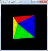
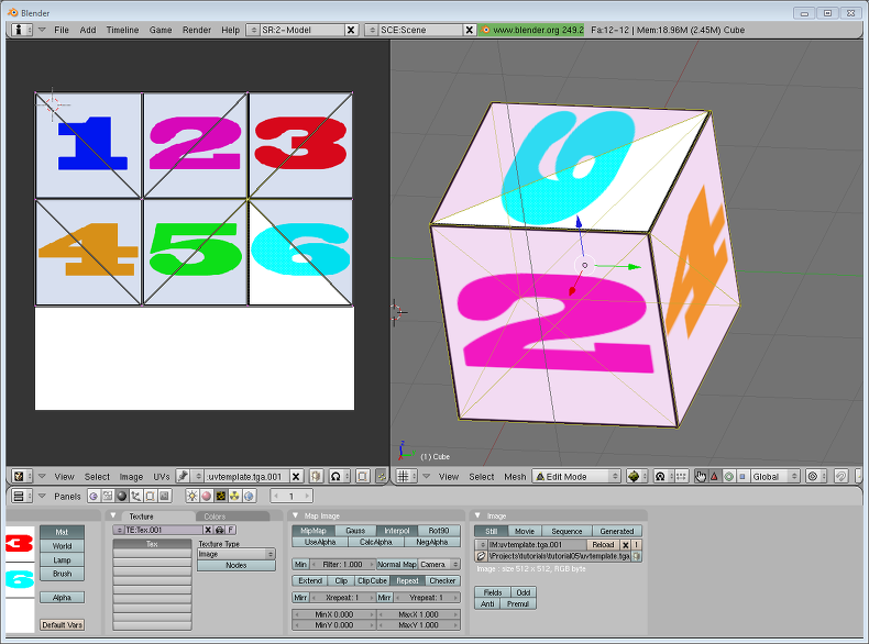
}64 * 64 크기의 대리석 표면 모양 이미지를 marble64.bmp 파일로 준비했다. 이미지의 각 부분을 피라미드의 각 정점에 적당히 대응시킨다. 피라미드의 꼭대기 정점에 이미지의 중앙을 대응시키고 나머지 모서리 정점에는 이미지의 같은 방향 모서리를 대응시켰다.
피라미드를 마루 바닥에 올려 놓고 대리석 모양이 그려진 보자기를 잘라서 위에서 그대로 씌운 것과 같다. 중심을 기준으로 피라미드의 각 변에 맞는 삼각형 조각을 입혔으므로 정면에서 보면 그냥 대리석 평면처럼 보이지만 회전해 보면 각 면의 경계가 드러난다.


텍스처 방식을 여러 가지로 변형하는 기능들이 미리 작성되어 있는데 다음 항에서 따로 상세하게 연구해 보자.
10-5.텍스처 맵핑 옵션
텍스처 맵핑은 굉장히 복잡한 연산이어서 선택할 수 있는 옵션들이 아주 많다. 다음 함수는 텍스처 맵핑 환경을 지정한다.
void glTexEnv[f, i](GLenum target, GLenum pname, GLfloat param);
target 인수는 어떤 환경을 조정할 것인가를 지정한다. GL_TEXTURE_ENV, GL_TEXTURE_FILTER_CONTROL, GL_POINT_SPRITE 중 하나이다. pname은 조정하고자 하는 옵션의 이름이고 param은 옵션의 값이다. GL_TEXTURE_ENV_MODE는 텍셀의 색상과 지오메트리의 색상을 결합하는 방식 지정하는데 다음 여섯 가지 방식이 있다.
| 방식 | 설명 |
| GL_MODULATE | 두 색상을 곱한다. |
| GL_REPLACE | 색상을 무시하고 텍스처로 덮어쓴다. |
| GL_ADD | 두 색상을 더한다. |
| GL_DECAL | |
| GL_BLEND | 블랜딩 색상과 텍스처를 혼합한다. |
| GL_COMBINE |
피라미드의 각 면에 고유의 색상이 지정되어 있는데 결합 모드에 따라 이 색상과 텍스처 색상의 연산이 결정된다. REPLACE로 덮어 쓰면 텍스처의 무늬만 나타나지만 MODULATE나 ADD로 혼합하면 면의 원래색과 논리적으로 섞인다. 팝업 메뉴로 모드를 바꿔 보자.

텍스처 이미지가 다각형을 덮어 버리는 것이 아니라 원래색과 섞이는 효과가 나타난다. 이 모드에서는 똑같은 텍스처라도 다각형의 원래 색에 따라 무늬의 색상이 결정되므로 하나의 텍스처로 노란색, 초록색 대리석을 표현할 수 있다.
다음 함수는 텍스처 파라미터를 지정하는데 이 파라미터에 따라 텍스처를 그리는 랜더링 방식이 달라진다.
void glTexParameter[f, i][v](GLenum target, GLenum pname, GLfloat param);
target은 텍스처의 차원을 지정한다. pname은 파라미터의 이름이고 param은 값이다. 텍스처와 물체의 면적이 정확하게 일치하는 경우가 드물므로 텍스처를 늘리거나 줄여서 입혀야 한다. 텍스처 맵으로부터 입힐 색상을 계산하는 과정을 텍스처 필터링이라고 한다. GL_TEXTURE_MIN_FILTER는 축소시의 필터링을 지정하고 GL_TEXTURE_MAG_FILTER는 확대시의 필터링을 지정한다. 주로 다음 두 가지 필터가 사용된다.
■ 최단거리(GL_NEAREST) : 비율상 대응되는 위치의 텍셀값을 그대로 사용한다. 알고리즘은 단순하지만 품질은 떨어진다.
■ 선형(GL_LINEAR) : 대응되는 위치 주변의 텍셀값에 대한 평균을 계산한다. 오버헤더가 많지만 품질은 훨씬 더 좋다.
축소시의 디폴트는 GL_NEAREST_MIPMAP_LINEAR이며 확대시의 디폴트는 GL_LINEAR이다. 예제에서는 의도적으로 64 크기의 작은 텍스처를 입혀 놓고 필터링을 토글해 보았다. 차이를 분명히 보고 싶으면 창을 크게 해서 도형을 확대한 상태로 필터링을 바꿔 보면 된다.

LINEAR 필터링은 부드럽게 확대되지만 NEAREST 필터링은 품질이 훨씬 더 거칠며 계단 현상도 나타난다. 물론 속도는 반대겠지만 이 정도 도형에서 속도차를 실감하기는 어렵다. 텍스처를 더 큰 것으로 사용하면 확대에 의한 부작용이 감소하므로 품질은 더 좋아진다.
GL_TEXTURE_WRAP_S, T, R 파라미터는 각 축에 대한 텍스처 랩핑 방식을 지정하며 다음값중 하나를 지정한다.
| 랩핑 | 설명 |
| GL_CLAMP | 경계 부근을 반복한다. |
| GL_CLAMP_TO_BORDER | 경계 텍셀의 값을 반복한다. |
| GL_CLAMP_TO_EDGE | |
| GL_MIRRORED_REPEAT | 반사된 모양으로 반복한다. |
| GL_REPEAT | 반복한다. |
텍스처 범위와 텍셀 범위가 일치하지 않을 경우 반복 및 경계 부근의 처리 방식을 지정한다. 이 예제는 텍스처가 다각형보다 작으므로 이 파라미터를 지정할 필요가 없다.
=================================
=================================
=================================
출처: http://m.blog.daum.net/aero2k/84

텍스쳐 적용하기 - 2D Texture
아마도 이글을 읽는 분들의 경우, 기본적으로 OpenGL 또는 OpenGL ES 1.x에서 텍스쳐 구현을 해보셨을 것이라 생각 됩니다.
OpenGL 책을 사면 텍스쳐에 대한 설명은 필수 적이기 때문에 관련 책을 읽어 보는 것을 추천합니다.
바른생활님의 설명하신 "[iOS GLView 만들기]13. Texturing" 장에서도 설명이 잘 되어 있습니다.
All about OpenGL ES 2.x – (part 2/3)
(http://db-in.com/blog/2011/02/all-about-opengl-es-2-x-part-23/)
여기서는 OpenGL ES 2.0에서 2D Texture 을 사용하기 위해서는 어떻게 처리해야 하는지에 대해서 좀더 집중하도록 하겠습니다.
1. Texture 그리기전 준비사항
텍스쳐의 종류에는 2D Texture, Multi Texture, Cubemap Texture, Bumpmap Texture 등등 다양한 방식이 있습니다.
(3D Texture도 있지만 이는 GL_TEXTURE_3D_OES 인 extension 임으로 생략...)
일반적으로 가장 많이 사용하는 2D Texture에 대해서 알아 보도록 하겠습니다.
텍스쳐를 그리기 위해서는 일차적으로는 해당 이미지 파일을 로딩한 후 buffer array로 변경해야 하며,
그 다음에는 Texture ID를 생성 한후 이 ID에 buffer array를 저장해야 합니다.
텍스쳐 ID 생성 및 이미지 RGBA 버퍼 저장
GLuint RenderingEngine::createTexture(const string& file, bool bPot, int wrapMode)

{

  GLuint tex;

  glGenTextures(1, &tex);

  glBindTexture(GL_TEXTURE_2D, tex);


  loadImage(m_resourceManager->LoadImage(file));


  GLenum minFilter = (bPot ? GL_LINEAR : GL_LINEAR_MIPMAP_LINEAR);

  glTexParameteri(GL_TEXTURE_2D, GL_TEXTURE_MIN_FILTER, minFilter);

  glTexParameteri(GL_TEXTURE_2D, GL_TEXTURE_MAG_FILTER, GL_LINEAR);


  if (bPot) {

    if (wrapMode == 1) {

      glTexParameteri(GL_TEXTURE_2D, GL_TEXTURE_WRAP_S, GL_CLAMP_TO_EDGE);

      glTexParameteri(GL_TEXTURE_2D, GL_TEXTURE_WRAP_T, GL_CLAMP_TO_EDGE);

    } else {

      glTexParameteri(GL_TEXTURE_2D, GL_TEXTURE_WRAP_S, GL_REPEAT);

      glTexParameteri(GL_TEXTURE_2D, GL_TEXTURE_WRAP_T, GL_REPEAT);

    }

  } else {

    //glTexParameteri(GL_TEXTURE_2D, GL_GENERATE_MIPMAP, GL_TRUE);

    glGenerateMipmap(GL_TEXTURE_2D);

  }

  return tex;

}
----------------------------------------------------------
코드의 구성은 OpenGL ES 1.x와 유사합니다.
(1) glGenTexture() 함수를 이용해서 Texture ID를 생성하고,
(2) glBindTexture() 함수를 이용해서 생성한 Texture ID를 방인딩하고,
(3) glTexImage2D() 함수를 이용해서 "16장 " 에서 얻은 RGBA byte array을 저장하고,
(4) glTexParameteri() 함수를 이용해서 축소필터 GL_TEXTURE_MIN_FILTER 과 확대 필터 GL_TEXTURE_MAG_FILTER 를 설정할 수 있습니다.
(5) glTexParameteri() 함수를 이용해서 GL_TEXTURE_WRAP_S, GL_TEXTURE_WRAP_T 를 이용해서 Vertex 점정의 경계 지점을 부드럽게 보간 시켜주는 GL_CLAMP_TO_EDGE 와 텍스쳐를 계속 반복 시킬 GL_REPEAT를 설정할 수 있습니다.
밉맵을 사용할 경우에는 glGenerateMipmap(GL_TEXTURE_2D) 를 이용해 주고요
축소 / 확대 필터
GL_NEAREST : 인접 축소 필터로, 가장 근접한 텍셀이 색상을 사용한다. 단순하고 거칠게 표현된다.
glTexParameteri(GL_TEXTURE_2D, GL_TEXTURE_MIN_FILTER, GL_NEAREST);
glTexParameteri(GL_TEXTURE_2D, GL_TEXTURE_MAG_FILTER, GL_NEAREST);
GL_LINEAR : 양방향 선형(bilinear) 필터링 알고리즘으로, 텍셀에서 인접한 2x2 점을 샘플링하여 가중치 평균값을 구한다.
glTexParameteri(GL_TEXTURE_2D, GL_TEXTURE_MIN_FILTER, GL_LINEAR);
glTexParameteri(GL_TEXTURE_2D, GL_TEXTURE_MAG_FILTER, GL_LINEAR);
GL_LINEAR_MIPMAP_LINEAR : 삼중 선형(TRILINEAR) 필터링으로 가장 근접한 밉맵 두개를 찾아서 각각 GL_LINEAR 필터링한한 결과 값을 섞는다. OpenGL은 이 필터링을 위해서 8개의 샘플을 추출하므로, 가장 높은 품질의 값을 생성하는 필터이다.
glTexParameteri(GL_TEXTURE_2D, GL_TEXTURE_MIN_FILTER, GL_LINEAR_MIPMAP_LINEAR);
glTexParameteri(GL_TEXTURE_2D, GL_TEXTURE_MAG_FILTER, GL_LINEAR);
밉맵은 축소필터에만 영향을 미치며, OpenGL ES 2.0에서 사용할 경우에는 자동 밉맵 함수인
glGenerateMipmap(GL_TEXTURE_2D); 이용해서 처리 가능하다.
이제 Texture ID를 생성하였음으로, 생성한 Texture ID를 이용해서 화면에 어떻게 렌더링 하는지에 대해서 알아보도록 하겠습니다.
2. 2D Texture
앞장까지의 강좌에서는 Vertex Coordination(정점 좌표)와 Normal Coordination(법선 좌표)를 다뤘었습니다.
정점 좌표를 이용해서 삼각형, 큐브, 원뿔, 구, 뫼뷔우스 띠 등과 같은 Geometry(기하)를 그렸으며,
법선 좌표를 이용해서 삼각형의 각 면등에 조명(Light) 효과를 보여줬었습니다.
마찬가지로 텍스쳐를 Geometry에 표현하기 위해서는 텍스쳐 좌표가 필요합니다.
(텍스쳐 좌표를 Texture Element라 부르며 짧게 텍셀(texel)이라고 합니다.)
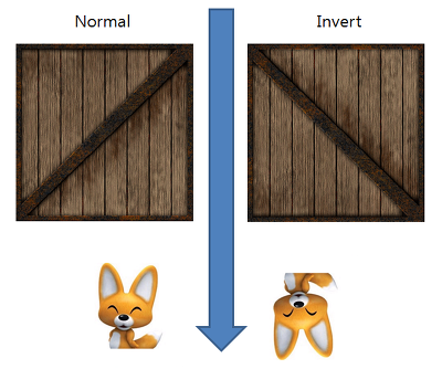
OpenGL에서 texel은 기존 pixel과 다릅니다.
다음의 그림을 보시면, 픽셀은 Left-Top이 원점(base point)입니다.
하지만, Open GL에서의 원점은 Left-Bottom 입니다.
(원점을 Anchor point 라고도 부르기도 합니다.)


상자와 에디 이미지를 예로 들어 보면 정상(normal) 이미지(pixel 순서)의 경우 왼쪽과 같으며, 이 이미지를 OpenGL에 저장하면,
오른쪽과 같이 뒤집혀서 들어가기 때문에 OpenGL로 화면을 그리면 뒤집혀 있게 됩니다.
해결 방법은 여러가지가 있습니다.
(1) 이미지 자체를 수직(세로) 방향으로 뒤집어서 저장해 둔다.
(2) 이미지를 읽은 후 Affine coordination(아핀 좌표계) 를 api 등을 이용해서 뒤집어서 OpenGL에 전달한다.
(3) OpenGL에서 이용할 texel의 y 좌표에 -1.0f 를 곱해 줌으로서 항상 뒤집어 지게 한다.
(4) Vertex Shader에서 vertex position에 해당하는 값("gl_Vertex.y" to "a_position.y")에 -1.0f를 곱해 줌으로서
항상 뒤집어 지게 한다. ("a_position"은 제가 이용하는 attribute vec4 a_position; 변수로서 변수명은 바꿔서 사용해도 됩니다. ^^;)
-----------------------------
여기서 주의할 점은 (3)번과 (4)번의 경우 Render To Texture를 이용해서 화면을 표현해 줄때 RTT한 이미지가 Left-Top으로 그려진
상태에서 텍셀의 y축에 음수가 곱해져서 Left-Bottom 순서로 다시 뒤집어지는 문제가 발생할 수도 있음으로,
제 개인적인 의견으로는 (1)번과 (2)번 방법이 적당할 것 같습니다.
3. Draw Banana
이제 바나나를 기준으로 실제 Shader을 이용해서 Texture Rendering 하는 부분에 대해서 보겠습니다.
렌더링의 절차를 그림으로 표현하면 다음과 같습니다.

(소스코드 분석에 앞서서 다음 장에서 다룰 MultiTexture와 혼합되어 있기 때문에 일반적인 방법과는 좀 다를 수 있습니다.)
Classes/RenderingEngine.CH03.ES20.cpp
렌더링 하기전 초기화 부분 정리
void RenderingEngine::Initialize(const vector<ISurface*>& surfaces)

{

...

  m_textures.BANANA = createTexture(TextureFiles[BANANA], true);  // ---- (1)


   // Initialize OpenGL ES STATE
   Initialize(width, height);  // ------------------- (4)

...

}


// ------------------- (2)

GLuint RenderingEngine::createTexture(const string& file, bool bPot, int wrapMode)
{
  GLuint tex;
  glGenTextures(1, &tex);
  glBindTexture(GL_TEXTURE_2D, tex);

  loadImage(m_resourceManager->LoadImage(file));  // ------------------- (3)

  GLenum minFilter = (bPot ? GL_LINEAR : GL_LINEAR_MIPMAP_LINEAR);
  glTexParameteri(GL_TEXTURE_2D, GL_TEXTURE_MIN_FILTER, minFilter);
  glTexParameteri(GL_TEXTURE_2D, GL_TEXTURE_MAG_FILTER, GL_LINEAR);

  if (bPot) {
    if (wrapMode == 1) {
      glTexParameteri(GL_TEXTURE_2D, GL_TEXTURE_WRAP_S, GL_CLAMP_TO_EDGE);
      glTexParameteri(GL_TEXTURE_2D, GL_TEXTURE_WRAP_T, GL_CLAMP_TO_EDGE);
    } else {
      glTexParameteri(GL_TEXTURE_2D, GL_TEXTURE_WRAP_S, GL_REPEAT);
      glTexParameteri(GL_TEXTURE_2D, GL_TEXTURE_WRAP_T, GL_REPEAT);
    }
  } else {
    //glTexParameteri(GL_TEXTURE_2D, GL_GENERATE_MIPMAP, GL_TRUE);
    glGenerateMipmap(GL_TEXTURE_2D);
  }

  return tex;
}
------------------------------------------------------
(1) : 바나나 텍스쳐 생성
createTexture() 함수를 이용해서 "banana.jpg" 파일을 읽은 후 Texture ID를 생성합니다.
이 생성한 Texture ID로 바나나를 3D로 렌더링 하기 전에 glBindTexture(GL_TEXTURE_2D, tex_id) 를 해주면 됩니다.
(렌더링 하기 전이란.. glDrawArrays나 glDrawElements 를 호출하기 전 이라고 보면 될것 같습니다.)
(2) : createTexture() 함수
위에서도 설명했었지만 텍스쳐 파일을 로딩한 후 Texture ID를 생성하는 함수 입니다.
주의할 실 점은 바른생활님 블로그에도 언급되었다 싶이, 밉맵 사용시에는 이미지 파일을 로딩한 후
OpenGL에 저장하는 함수인 glTexImage2D() 함수 처리를 앞에서 먼저 해 줘야 정상적으로 동작합니다.
(3) : loadImage() 함수
파일을 로딩하고 array buffer를 glTexImage2D()함수를 이용해서 OpenGL에 저장하는 역활을 합니다.
(4) : Initialize() 함수
OpenGL ES20과 관련한 VERTEX SHADER, FRAGMENT SHADER STATE를 초기화는 부분입니다.
이전 장과 다른 점은 texture를 사용할 것임으로 다음과 같이 두가지가 추가 됩니다.
VERTEX SHADER에 선언된 texel 과 관련한 attribute 형인 "attribute vec2 a_textureCoordIn;"와 연결되는
m_pixelLight.Attributes.TextureCoord = glGetAttribLocation(program, "a_textureCoordIn");
부분과 FRAGMENT SHADER에 선언된 sampler2D 형인 "uniform sampler2D Sampler0;"와 연결되는
glUniform1i(m_pixelLight.Uniforms.Sampler0, 0);
를 추가 되었습니다.
(Texture를 다룰 때 sampler2D형인 Sampler0에 0값으로 초기화 해주지 않는 책이나 코드가 간혹 있습니다.
Single Texture일 경우에는 0으로 초기화 해주지 않아도 정상적으로 동작은 합니다.
하지만 Multi Texture 까지 고려해서 프로그램을 짤 것임으로 Sampler0에는 0으로 초기화 해주는 것이 좋습니다.)
Classes/RenderingEngine.CH03.ES20.cpp
렌더링 부분 정리
void RenderingEngine::Render(const vector < Visual > & visuals)

{

    ...

    // PixelLight
    bool bIsPixelLight = true; // ---- (1)
    ProgramHandles handler;
    handler = m_pixelLight;
    glUseProgram(handler.Program);

    // Initialize various state.

    glEnableVertexAttribArray(handler.Attributes.Position);

    glEnableVertexAttribArray(handler.Attributes.Normal);

    glEnableVertexAttribArray(handler.Attributes.TextureCoord); // ---- (2)

    ...

    // Set the Texture Mode
    if (bIsPixelLight) {
        glActiveTexture(GL_TEXTURE0 + TEXTURE_0);
        if (visualIndex == 9) {
            glBindTexture(GL_TEXTURE_2D, m_textures.BANANA); // --------- (3)
            glUniform1i(handler.Uniforms.Sampler0, TEXTURE_0);
        } else {
            glBindTexture(GL_TEXTURE_2D, m_textures.CRATE);
            glUniform1i(handler.Uniforms.Sampler0, TEXTURE_0);
        }
    }

    ...

    // Draw the surface.

    int stride = 2 * sizeof(vec3) + sizeof(vec2); // --------- (4)
    GLvoid * offset = (GLvoid * ) sizeof(vec3); // --------- (5)
    GLint position = handler.Attributes.Position;
    GLint normal = handler.Attributes.Normal;
    GLint texture = handler.Attributes.TextureCoord; // --------- (6)

    vec4 white(1, 1, 1, 1);
    if (drawable.IndexCount < 0) {
        glBindBuffer(GL_ARRAY_BUFFER, drawable.VertexBuffer);
        glVertexAttribPointer(position, 3, GL_FLOAT, GL_FALSE, stride, 0);
        glVertexAttribPointer(normal, 3, GL_FLOAT, GL_FALSE, stride, offset);
        offset = (GLvoid * )(sizeof(vec3) * 2); // --------- (7)
        glVertexAttribPointer(texture, 2, GL_FLOAT, GL_FALSE, stride, offset); // --------- (8)
        glDrawArrays(GL_TRIANGLES, 0, drawable.VertexCount); // --------- (9)

    } else {

        // --------- (10)
        glBindBuffer(GL_ARRAY_BUFFER, drawable.VertexBuffer);
        glVertexAttribPointer(position, 3, GL_FLOAT, GL_FALSE, stride, 0);
        glVertexAttribPointer(normal, 3, GL_FLOAT, GL_FALSE, stride, offset);
        offset = (GLvoid * )(sizeof(vec3) * 2);
        glVertexAttribPointer(texture, 2, GL_FLOAT, GL_FALSE, stride, offset);
        glBindBuffer(GL_ELEMENT_ARRAY_BUFFER, drawable.IndexBuffer);
        glDrawElements(GL_TRIANGLES, drawable.IndexCount, GL_UNSIGNED_SHORT, 0);

    }

    glDisableVertexAttribArray(handler.Attributes.Position);
    glDisableVertexAttribArray(handler.Attributes.Normal);
    glDisableVertexAttribArray(handler.Attributes.TextureCoord); // --------- (11)

    // VBO을 UnBind 해야 VBA와 충돌이 없다.  // --------- (12)
    glBindBuffer(GL_ARRAY_BUFFER, 0);
    glBindBuffer(GL_ELEMENT_ARRAY_BUFFER, 0);

    /* Flush all drawings */
    glFinish();

    error = checkGLError();

    if (!m_spinning) {
        xrot += xspeed; /* Add xspeed To xrot */
        yrot += yspeed; /* Add yspeed To yrot */
    }

    glBindTexture(GL_TEXTURE_2D, 0); // --------- (13)
    glUseProgram(0); // --------- (14)

}
------------------------------------------------------
(1) : bIsPixelLight 변수 설정합니다.
bool bIsPixelLight = true;
handler = m_pixelLight;
glUseProgram(handler.Program);
(2) Texture Coordination Array 를 활성화 해줍니다.
"glEnableVertexAttribArray(handler.Attributes.TextureCoord);"
기존 GLES1.1 기준으로는 "glEnableClientState(GL_TEXTURE_COORD_ARRAY);" 함수를 대체하는 부분입니다.
활성화와 반대되는 비 활성화는 (11)번 함수" glDisableVertexAttribArray(handler.Attributes.TextureCoord);"가
쌍으로 있어야 합니다.
(3) Banana texture id를 바인딩 해줍니다.
생성한 텍스쳐를 3D 렌더링 객체에 적용하기 위해서는 해당 texture id를 바인딩 해줘야 합니다.
glBindTexture(GL_TEXTURE_2D, m_textures.BANANA);
glUniform1i(handler.Uniforms.Sampler0, TEXTURE_0);
(Sampler0에 대해서 0번으로 재 설정 해주는 부분은 없어도 상관은 없지만, 명시적 표현으로 나뒀습니다.)
(간혹 Shader에 정의된 sampler2d 변수에 glGenTexture() 함수를 이용해서 생성한 texture id에 -1를 한 후
넣어주는 코드가 있는 경우가 있습니다. 이는 glGen()시에 처음 생성된 ID가 1이기 때문에 그렇게 하는 경우입니다.
문제는 Galaxy Tab과 같은 PowerVR GPU의 경우, 처음 생성시 1이 아닌 3xxxxx 번 등과 같은 높은 숫자가 나오는 경우가
있습니다. 그럼으로 명시적으로 그냥 첫 번째 sampler2d 변수에는 0을 두 번째는 1를 넣어주는 것이 좋을 것 같습니다.)
(4) Vertex, Normal, Texture coord 에 대한 memory chunk 영역을 설정 해 줍니다.
banana.obj를 해석한 후 Vertex Buffer Object(VBO)에 저장해 놓았음으로, OpenGL에게 메모리가 한 묶음에 해당하는
크기를 알려줘야 합니다. 이 역할을 하는 부분이 stride 입니다.
int stride = 2 * sizeof(vec3) + sizeof(vec2);
"VertexCoord(12) + NormalCoord(12) + TextureCoord(8) = 32" 가 됩니다.
OpenGL ES 2.0 Programming Guide 책에서는 이부분을 Array Of Structures(Page 104) 라고 표현 합니다.
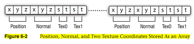
(5) Array Of Structures 에서 Normal Coord에 대한 offset 을 설정 합니다.
GLvoid* offset = (GLvoid*) sizeof(vec3);
VertexCoord 에 대한 크기 만큼 이동시켜줄 것임으로 12 bytes 입니다.
전달은 GLvoid* 형태로 캐스팅해서 주소로 넘겨 줍니다.
(6) VERTEX SHADER내의 Texture Attrbute와 연결된 ID 입니다.
GLint texture = handler.Attributes.TextureCoord;
PixelLighting.vert 내에 선언된 "a_attribute vec2 a_textureCoordIn;" 연결 가능한 Attribute ID 입니다.
이 ID를 이용해서 (8)번 항목에서 Vertex Attribute Pointer 등록 시 사용하게 됩니다.
(7) Array Of Structures 에서 Texture Coord에 대한 offset 을 설정 합니다.
offset = (GLvoid*) (sizeof(vec3) * 2);
VertexCoord 와 NormalCoord에 대한 크기 만큼 이동시켜줄 것임으로 24 bytes 입니다.
전달은 GLvoid* 형태로 캐스팅해서 주소로 넘겨 줍니다.
(8) 텍셀 정보를 저장 합니다.
텍셀 좌표에 대한 정보를 "glVertexAttribPointer(texture, 2, GL_FLOAT, GL_FALSE, stride, offset);"
함수를 이용해서 저장합니다.
기존 GLES1.1 기준으로는 "glTexCoordPointer(2, GL_FLOAT, 0, texcoords);"함수를 대체하는 부분입니다.
(9) Vertices 방식으로 렌더링을 합니다.
glDrawArrays(GL_TRIANGLES, 0, drawable.VertexCount);
banana.obj는 glDrawArray 방식으로 표출되게금 header 형태로 만들었기 때문에 이 부분에서 그려지게 됩니다.
(10) Indices 방식으로 렌더링을 합니다.
glDrawElements(GL_TRIANGLES, drawable.IndexCount, GL_UNSIGNED_SHORT, 0);
ParametricSurface 로 만들어진 Geometry 들은 Indices 로 만들어 졌음으로 이 부분에서 그려지게 됩니다.
(11) Texture Coordination Array 를 비 활성화 해줍니다.
"glDisableVertexAttribArray(handler.Attributes.TextureCoord);"
함수는 기존 GLES1.1 기준으로는 "glDisableClientState(GL_TEXTURE_COORD_ARRAY);" 함수를 대체하는 부분입니다.
비 활성화와 반대되는 활성화는 (2)번 함수"glEnableVertexAttribArray(handler.Attributes.TextureCoord);"가
쌍으로 있어야 합니다.
(12) VBO 객체를 UnBind 합니다.
Vertex Buffer Array 형태로 그려지는 렌더러와 충돌 하지 않도록 VBO를 해제해 줍니다.
(13) 바인딩 했던 텍스쳐를 해제해 줍니다.
glBindTexture(GL_TEXTURE_2D, 0);
(14) PixelLighting 쉐이더를 해제해 줍니다.
glUseProgram(0);
4. 좀더 파고들기
추가적으로 이미지 뒤집기 기능을 좀더 정리해 보도록 하겠습니다.
이미지 뒤집기 API 정리
앞에서 언급했지만, 이미지 파일를 로딩한 후 raw data를 뒤집을 필요가 있습니다.
이때 이용하는 것이 Affine Transformation API 입니다.
일반적으로 아이폰에서는 다음과 같이 적용하면 됩니다.
TextureDescription LoadImage(const string& file)

{

    NSString* basePath = [NSString stringWithUTF8String:file.c_str()];

    NSString* resourcePath = [[NSBundle mainBundle] resourcePath];

    NSString* fullPath = [resourcePath stringByAppendingPathComponent:basePath];

    UIImage* uiImage = [UIImage imageWithContentsOfFile:fullPath];


    TextureDescription description;

    description.Size.x = CGImageGetWidth(uiImage.CGImage);

    description.Size.y = CGImageGetHeight(uiImage.CGImage);

    description.BitsPerComponent = 8;

    description.Format = TextureFormatRgba;

    description.MipCount = 1;


    int bpp = description.BitsPerComponent / 2;

    int byteCount = description.Size.x * description.Size.y * bpp;

    unsigned char* data = (unsigned char*)calloc(byteCount, 1);


    CGAffineTransform    transform = CGAffineTransformIdentity;

    //if (flipImage)

    {

      transform = CGAffineTransformTranslate(transform, 0,  description.Size.y);

      transform = CGAffineTransformScale(transform, 1.0, -1.0);

    }

    CGColorSpaceRef colorSpace = CGColorSpaceCreateDeviceRGB();

    CGBitmapInfo bitmapInfo = kCGImageAlphaPremultipliedLast | kCGBitmapByteOrder32Big;

    CGContextRef context = CGBitmapContextCreate(data,

        description.Size.x, description.Size.y, description.BitsPerComponent, bpp * description.Size.x,

        colorSpace, bitmapInfo);

    CGContextConcatCTM(context, transform);

    CGColorSpaceRelease(colorSpace);

    CGRect rect = CGRectMake(0, 0, description.Size.x, description.Size.y);

    CGContextDrawImage(context, rect, uiImage.CGImage);

    CGContextRelease(context);


    m_imageData = [NSData dataWithBytesNoCopy:data length:byteCount freeWhenDone:YES];

    return description;

}
안드로이드에서는 다음과 같이 적용할 수 있습니다.
com.myastro.gles.ResourceManager.java
public ResourceManager(Context context, int res)

{
    // Get the texture from the Android resource directory
    Bitmap bitmap = null;
    InputStream is = context.getResources().openRawResource(res);

    try {
      // BitmapFactory is an Android graphics utility for images
      bitmap = BitmapFactory.decodeStream(is);
    } finally {
       //Always clear and close
       try {
        is.close();
        is = null;
       } catch (IOException e) {
     }
  }
  // 비트맵 변환을 위한 행렬을 만든다.
  Matrix mirrorMatrix = new Matrix();

  // 행렬 좌표를 Y축으로 뒤집는다.
  mirrorMatrix.preScale(1.0f, -1.0f);

  // 생성된 변환행렬을 이용해서 새로 bitmap을 생성한다. 속도는???
  Bitmap tranformedBitmap = Bitmap.createBitmap(bitmap, 0, 0, bitmap.getWidth(), bitmap.getHeight(), mirrorMatrix, false);
  bitmap.recycle();
  if (tranformedBitmap != null) {
    initBitmap(tranformedBitmap);
  }
}
5. 결론
텍스쳐 적용하기를 다루면서 어떻게 정리할까 고민했는데, 대략적인 정리가 된것 같네요.
텍스쳐 장은 책에서 이미 많이 소개하고 있는 부분이어서 OpenGL 책을 보시는게 이해가 더 빠를 수도 있습니다.
여기에 정리된 사항은 책을 보고 만들어 보시고 이런 방식으로 ES2.0으로 적용도 가능 하다는 관점으로 보시면 좋을 것 같습니다.
또한 제가 정리한 방식은 최적화 되어 있지 않음으로 참조만 하시기 바랍니다. ^^;
OGLES20 Template Application ported to mfc and android
http://code.google.com/p/myastro/downloads/list
=================================
=================================
=================================
출처: http://www.androidpub.com/2272636
1.gl.glGenTextures(1, mTextures, 0);
2.gl.glBindTexture(GL10.GL_TEXTURE_2D, mTextures[0]);
3.gl.glTexParameterf(GL10.GL_TEXTURE_2D, GL10.GL_TEXTURE_MIN_FILTER, GL10.GL_NEAREST);
4.gl.glTexParameterf(GL10.GL_TEXTURE_2D, GL10.GL_TEXTURE_MAG_FILTER, GL10.GL_LINEAR);
5.GLUtils.texImage2D(GL10.GL_TEXTURE_2D, 0, bitmap, 0);
6.bitmap.recycle();
gl은 GL10객체, bitmap은 Bitmap객체, mTextures는 int array(int [])일 때
하나의 텍스쳐를 위와 같이 로드할 수 있는건 알 것 같습니다.
그런데 매번 이미지를 위 소스를 통해 로드하는건 아무래도 효율적이지 못하고 그렇게 사용하라고 만든건 아닌것 같아서요.
로드해두고 해당 로드값마다 id를 줘서 빠르게 로딩할 수 있을 것 같은데(SoundPool 사용과 비슷하게) 방법을 모르겠네요.
영어가 안되니 원문 레퍼런스는 해석조차 안되니 더더욱이요 ㅠㅠ
제가 함수명과 파라미터로 추측하는건
glGenTextures : 로드된 텍스쳐의 index id를 mTextures에 저장하겠다
glBindTexture : 2D Type으로 mTextures[0]번째 id를 사용하겠다
glTexParameterf : 기타 설정 세팅
GLUtils.texImages2D : 현재 바인드되어 있는 texture에 bitmap을 세팅
당장 이렇게 어거지로 해석하고 있습니다.
만약 여러개의 텍스쳐를 로딩해두고 사용한다면 초기에 중복으로 해줘야할 일과 중복을 제거해서 해줘야 할일
마지막으로 로딩할 때 해줘야 할 일까지 구분해서 테스트 해보고 싶습니다.
아시는 분은 도와주시면 감사하겠습니다!
-------------------------------------------------------------------------------------------------------------------------------------------------------------
아래 코드를 참고하세요.
int[] texture = new int[TEX_NUM];
...
/* 초기화 함수내 */
gl.glGenTextures(TEX_NUM, texture, 0);
gl.glBindTexture(GL10.GL_TEXTURE_2D, texture[0]);
gl.glTexParameterx(GL10.GL_TEXTURE_2D, GL10.GL_TEXTURE_MIN_FILTER, GL10.GL_LINEAR);
gl.glTexParameterx(GL10.GL_TEXTURE_2D, GL10.GL_TEXTURE_MAG_FILTER, GL10.GL_LINEAR);
bitmap = BitmapFactory.decodeStream(mContext.getResources().openRawResource(R.drawable.background));
GLUtils.texImage2D(GL10.GL_TEXTURE_2D, 0, bitmap, 0);
bitmap.recycle();
gl.glBindTexture(GL10.GL_TEXTURE_2D, texture[1]);
gl.glTexParameterx(GL10.GL_TEXTURE_2D, GL10.GL_TEXTURE_MIN_FILTER, GL10.GL_LINEAR);
gl.glTexParameterx(GL10.GL_TEXTURE_2D, GL10.GL_TEXTURE_MAG_FILTER, GL10.GL_LINEAR);
bitmap = BitmapFactory.decodeStream(mContext.getResources().openRawResource(R.drawable.player));
GLUtils.texImage2D(GL10.GL_TEXTURE_2D, 0, bitmap, 0);
bitmap.recycle();
gl.glBindTexture(GL10.GL_TEXTURE_2D, texture[2]);
gl.glTexParameterx(GL10.GL_TEXTURE_2D, GL10.GL_TEXTURE_MIN_FILTER, GL10.GL_LINEAR);
gl.glTexParameterx(GL10.GL_TEXTURE_2D, GL10.GL_TEXTURE_MAG_FILTER, GL10.GL_LINEAR);
bitmap = BitmapFactory.decodeStream(mContext.getResources().openRawResource(R.drawable.box));
GLUtils.texImage2D(GL10.GL_TEXTURE_2D, 0, bitmap, 0);
bitmap.recycle();
/* 실제 사용하는 부분 */
gl.glEnable(GL10.GL_TEXTURE_2D);
gl.glBindTexture(GL10.GL_TEXTURE_2D, texture[0]); /* background */
gl.glTexCoordPointer(2, GL10.GL_FLOAT, 0, fb[1]);
gl.glVertexPointer(2, GL10.GL_FLOAT, 0, fb[0]);
gl.glDrawArrays(GL10.GL_TRIANGLE_STRIP, 0, 4);

2012.08.15 23:33:30
저임ㅋ
정말 감사드립니다!
바로 복사만 해서 사용할 수 있을정도로 정리가 되어있네요 ㅠㅠ
몇번 작성해보고 익혀야갰네요 ^^
다시 한번 감사드립니다~~!

2012.08.16 00:03:41
저임ㅋ
궁금한 점이 하나 더 생겼는데 괜찮으시면 답변 부탁드립니다.
텍스쳐 로딩을 구현하는 위치와 실행하는 위치가 궁금합니다.
일단 제가 블로그 등으로 공부한 곳에서 로딩은 하나의 물체를 그려주는 곳(vertex를 가지고 사각형 혹은 큐브 등을 그리는)에서 각각 로딩을 구현했고
Renderer를 구현한 클래스의 onSurfaceCreated에서 실행을 했는데 효율적인 방법 하나만 추천해주실 수 있나요?

2012.08.16 10:14:28
즐거운인생
(추천: 1 / 0)
말씀하신대로 하면 될 것 같은데요? ^^
저는.. onSurfaceCreated에서 texture 로딩 해놓고, 각 3D 객체, 예를 들면 Player 등에서 textureId를 변수로 두고, draw 함수에서 textureId로 바인딩해서 쓰고 있습니다.

2012.08.16 11:34:40
저임ㅋ
감사합니다^.^
덕분에 답답함이 싹 가신것 같네요
책없이 공부하니 힘이드네요ㅎㅎㅎ
좋은 하루되세요!!

2013.02.06 00:01:27
adb
정말 감사합니다ㅠ 몇일동안 찾아도 없었는데 드디어 여기서 찾는군요ㅠㅠ;;
사용법까지 상세해서 정말 얼마 안걸렸네요.
다시 한번 감사드리고요 언제나 행복하세요!!
=================================
=================================
=================================
출처: http://www.opengl-tutorial.org/kr/beginners-tutorials/tutorial-5-a-textured-cube/
Tutorial 5 : A Textured Cube
In this tutorial, you will learn :
- What are UV coordinates
- How to load textures yourself
- How to use them in OpenGL
- What is filtering and mipmapping, and how to use them
- How to load texture more robustly with GLFW
- What the alpha channel is
About UV coordinates
When texturing a mesh, you need a way to tell to OpenGL which part of the image has to be used for each triangle. This is done with UV coordinates.
Each vertex can have, on top of its position, a couple of floats, U and V. These coordinates are used to access the texture, in the following way :

Notice how the texture is distorted on the triangle.
Loading .BMP images yourself
Knowing the BMP file format is not crucial : plenty of libraries can load BMP files for you. But it’s very simple and can help you understand how things work under the hood. So we’ll write a BMP file loader from scratch, so that you know how it works, and never use it again.
Here is the declaration of the loading function :
GLuint loadBMP_custom(const char * imagepath);
so it’s used like this :
GLuint image = loadBMP_custom("./my_texture.bmp");
Let’s see how to read a BMP file, then.
First, we’ll need some data. These variable will be set when reading the file.
// Data read from the header of the BMP file unsigned char header[54]; // Each BMP file begins by a 54-bytes header unsigned int dataPos; // Position in the file where the actual data begins unsigned int width, height; unsigned int imageSize; // = width*height*3 // Actual RGB data unsigned char * data;
We now have to actually open the file
// Open the file FILE * file = fopen(imagepath,"rb"); if (!file){printf("Image could not be opened\n"); return 0;}
The first thing in the file is a 54-bytes header. It contains information such as “Is this file really a BMP file?”, the size of the image, the number of bits per pixel, etc. So let’s read this header :
if ( fread(header, 1, 54, file)!=54 ){ // If not 54 bytes read : problem printf("Not a correct BMP file\n"); return false; }
The header always begins by BM. As a matter of fact, here’s what you get when you open a .BMP file in a hexadecimal editor :
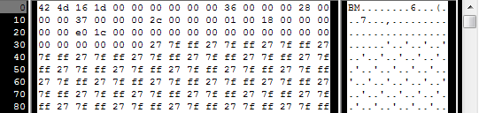
So we have to check that the two first bytes are really ‘B’ and ‘M’ :
if ( header[0]!='B' || header[1]!='M' ){ printf("Not a correct BMP file\n"); return 0; }
Now we can read the size of the image, the location of the data in the file, etc :
// Read ints from the byte array dataPos = *(int*)&(header[0x0A]); imageSize = *(int*)&(header[0x22]); width = *(int*)&(header[0x12]); height = *(int*)&(header[0x16]);
We have to make up some info if it’s missing :
// Some BMP files are misformatted, guess missing information if (imageSize==0) imageSize=width*height*3; // 3 : one byte for each Red, Green and Blue component if (dataPos==0) dataPos=54; // The BMP header is done that way
Now that we know the size of the image, we can allocate some memory to read the image into, and read :
// Create a buffer data = new unsigned char [imageSize]; // Read the actual data from the file into the buffer fread(data,1,imageSize,file); //Everything is in memory now, the file can be closed fclose(file);
We arrive now at the real OpenGL part. Creating textures is very similar to creating vertex buffers : Create a texture, bind it, fill it, and configure it.
In glTexImage2D, the GL_RGB indicates that we are talking about a 3-component color, and GL_BGR says how exactly it is represented in RAM. As a matter of fact, BMP does not store Red->Green->Blue but Blue->Green->Red, so we have to tell it to OpenGL.
// Create one OpenGL texture GLuint textureID; glGenTextures(1, &textureID); // "Bind" the newly created texture : all future texture functions will modify this texture glBindTexture(GL_TEXTURE_2D, textureID); // Give the image to OpenGL glTexImage2D(GL_TEXTURE_2D, 0,GL_RGB, width, height, 0, GL_BGR, GL_UNSIGNED_BYTE, data); glTexParameteri(GL_TEXTURE_2D, GL_TEXTURE_MAG_FILTER, GL_NEAREST); glTexParameteri(GL_TEXTURE_2D, GL_TEXTURE_MIN_FILTER, GL_NEAREST);
We’ll explain those last two lines later. Meanwhile, on the C++-side, you can use your new function to load a texture :
GLuint Texture = loadBMP_custom("uvtemplate.bmp");
Another very important point :** use power-of-two textures !**
- good : 128*128, 256*256, 1024*1024, 2*2…
- bad : 127*128, 3*5, …
- okay but weird : 128*256
Using the texture in OpenGL
We’ll have a look at the fragment shader first. Most of it is straightforward :
#version 330 core // Interpolated values from the vertex shaders in vec2 UV; // Ouput data out vec3 color; // Values that stay constant for the whole mesh. uniform sampler2D myTextureSampler; void main(){ // Output color = color of the texture at the specified UV color = texture( myTextureSampler, UV ).rgb; }
Three things :
- The fragment shader needs UV coordinates. Seems fair.
- It also needs a “sampler2D” in order to know which texture to access (you can access several texture in the same shader)
- Finally, accessing a texture is done with texture(), which gives back a (R,G,B,A) vec4. We’ll see about the A shortly.
The vertex shader is simple too, you just have to pass the UVs to the fragment shader :
#version 330 core // Input vertex data, different for all executions of this shader. layout(location = 0) in vec3 vertexPosition_modelspace; layout(location = 1) in vec2 vertexUV; // Output data ; will be interpolated for each fragment. out vec2 UV; // Values that stay constant for the whole mesh. uniform mat4 MVP; void main(){ // Output position of the vertex, in clip space : MVP * position gl_Position = MVP * vec4(vertexPosition_modelspace,1); // UV of the vertex. No special space for this one. UV = vertexUV; }
Remember “layout(location = 1) in vec2 vertexUV” from Tutorial 4 ? Well, we’ll have to do the exact same thing here, but instead of giving a buffer (R,G,B) triplets, we’ll give a buffer of (U,V) pairs.
// Two UV coordinatesfor each vertex. They were created with Blender. You'll learn shortly how to do this yourself. static const GLfloat g_uv_buffer_data[] = { 0.000059f, 1.0f-0.000004f, 0.000103f, 1.0f-0.336048f, 0.335973f, 1.0f-0.335903f, 1.000023f, 1.0f-0.000013f, 0.667979f, 1.0f-0.335851f, 0.999958f, 1.0f-0.336064f, 0.667979f, 1.0f-0.335851f, 0.336024f, 1.0f-0.671877f, 0.667969f, 1.0f-0.671889f, 1.000023f, 1.0f-0.000013f, 0.668104f, 1.0f-0.000013f, 0.667979f, 1.0f-0.335851f, 0.000059f, 1.0f-0.000004f, 0.335973f, 1.0f-0.335903f, 0.336098f, 1.0f-0.000071f, 0.667979f, 1.0f-0.335851f, 0.335973f, 1.0f-0.335903f, 0.336024f, 1.0f-0.671877f, 1.000004f, 1.0f-0.671847f, 0.999958f, 1.0f-0.336064f, 0.667979f, 1.0f-0.335851f, 0.668104f, 1.0f-0.000013f, 0.335973f, 1.0f-0.335903f, 0.667979f, 1.0f-0.335851f, 0.335973f, 1.0f-0.335903f, 0.668104f, 1.0f-0.000013f, 0.336098f, 1.0f-0.000071f, 0.000103f, 1.0f-0.336048f, 0.000004f, 1.0f-0.671870f, 0.336024f, 1.0f-0.671877f, 0.000103f, 1.0f-0.336048f, 0.336024f, 1.0f-0.671877f, 0.335973f, 1.0f-0.335903f, 0.667969f, 1.0f-0.671889f, 1.000004f, 1.0f-0.671847f, 0.667979f, 1.0f-0.335851f };
The UV coordinates above correspond to the following model :
The rest is obvious. Generate the buffer, bind it, fill it, configure it, and draw the Vertex Buffer as usual. Just be careful to use 2 as the second parameter (size) of glVertexAttribPointer instead of 3.
This is the result :

and a zoomed-in version :

What is filtering and mipmapping, and how to use them
As you can see in the screenshot above, the texture quality is not that great. This is because in loadBMP_custom, we wrote :
glTexParameteri(GL_TEXTURE_2D, GL_TEXTURE_MAG_FILTER, GL_NEAREST); glTexParameteri(GL_TEXTURE_2D, GL_TEXTURE_MIN_FILTER, GL_NEAREST);
This means that in our fragment shader, texture() takes the texel that is at the (U,V) coordinates, and continues happily.

There are several things we can do to improve this.
Linear filtering
With linear filtering, texture() also looks at the other texels around, and mixes the colours according to the distance to each center. This avoids the hard edges seen above.

This is much better, and this is used a lot, but if you want very high quality you can also use anisotropic filtering, which is a bit slower.
Anisotropic filtering
This one approximates the part of the image that is really seen through the fragment. For instance, if the following texture is seen from the side, and a little bit rotated, anisotropic filtering will compute the colour contained in the blue rectangle by taking a fixed number of samples (the “anisotropic level”) along its main direction.

Mipmaps
Both linear and anisotropic filtering have a problem. If the texture is seen from far away, mixing only 4 texels won’t be enough. Actually, if your 3D model is so far away than it takes only 1 fragment on screen, ALL the texels of the image should be averaged to produce the final color. This is obviously not done for performance reasons. Instead, we introduce MipMaps :

- At initialisation time, you scale down your image by 2, successively, until you only have a 1x1 image (which effectively is the average of all the texels in the image)
- When you draw a mesh, you select which mipmap is the more appropriate to use given how big the texel should be.
- You sample this mipmap with either nearest, linear or anisotropic filtering
- For additional quality, you can also sample two mipmaps and blend the results.
Luckily, all this is very simple to do, OpenGL does everything for us provided that you ask him nicely :
// When MAGnifying the image (no bigger mipmap available), use LINEAR filtering glTexParameteri(GL_TEXTURE_2D, GL_TEXTURE_MAG_FILTER, GL_LINEAR); // When MINifying the image, use a LINEAR blend of two mipmaps, each filtered LINEARLY too glTexParameteri(GL_TEXTURE_2D, GL_TEXTURE_MIN_FILTER, GL_LINEAR_MIPMAP_LINEAR); // Generate mipmaps, by the way. glGenerateMipmap(GL_TEXTURE_2D);
How to load texture with GLFW
Our loadBMP_custom function is great because we made it ourselves, but using a dedicated library is better. GLFW2 can do that too (but only for TGA files, and this feature has been removed in GLFW3, that we now use) :
GLuint loadTGA_glfw(const char * imagepath){ // Create one OpenGL texture GLuint textureID; glGenTextures(1, &textureID); // "Bind" the newly created texture : all future texture functions will modify this texture glBindTexture(GL_TEXTURE_2D, textureID); // Read the file, call glTexImage2D with the right parameters glfwLoadTexture2D(imagepath, 0); // Nice trilinear filtering. glTexParameteri(GL_TEXTURE_2D, GL_TEXTURE_WRAP_S, GL_REPEAT); glTexParameteri(GL_TEXTURE_2D, GL_TEXTURE_WRAP_T, GL_REPEAT); glTexParameteri(GL_TEXTURE_2D, GL_TEXTURE_MAG_FILTER, GL_LINEAR); glTexParameteri(GL_TEXTURE_2D, GL_TEXTURE_MIN_FILTER, GL_LINEAR_MIPMAP_LINEAR); glGenerateMipmap(GL_TEXTURE_2D); // Return the ID of the texture we just created return textureID; }
Compressed Textures
At this point, you’re probably wondering how to load JPEG files instead of TGA.
Short answer : don’t. GPUs can’t understand JPEG. So you’ll compress your original image in JPEG, and decompress it so that the GPU can understand it. You’re back to raw images, but you lost image quality while compressing to JPEG.
There’s a better option.
Creating compressed textures
- Download The Compressonator, an AMD tool
- Load a Power-Of-Two texture in it
- Generate mipmaps so that you won’t have to do it on runtime
- Compress it in DXT1, DXT3 or in DXT5 (more about the differences between the various formats on Wikipedia) :

- Export it as a .DDS file.
At this point, your image is compressed in a format that is directly compatible with the GPU. Whenever calling texture() in a shader, it will uncompress it on-the-fly. This can seem slow, but since it takes a LOT less memory, less data needs to be transferred. But memory transfers are expensive; and texture decompression is free (there is dedicated hardware for that). Typically, using texture compression yields a 20% increase in performance. So you save on performance and memory, at the expense of reduced quality.
Using the compressed texture
Let’s see how to load the image. It’s very similar to the BMP code, except that the header is organized differently :
GLuint loadDDS(const char * imagepath){

    unsigned char header[124];

    FILE *fp;

    /* try to open the file */
    fp = fopen(imagepath, "rb");
    if (fp == NULL)
        return 0;

    /* verify the type of file */
    char filecode[4];
    fread(filecode, 1, 4, fp);
    if (strncmp(filecode, "DDS ", 4) != 0) {
        fclose(fp);
        return 0;
    }

    /* get the surface desc */
    fread(&header, 124, 1, fp);

    unsigned int height      = *(unsigned int*)&(header[8 ]);
    unsigned int width         = *(unsigned int*)&(header[12]);
    unsigned int linearSize     = *(unsigned int*)&(header[16]);
    unsigned int mipMapCount = *(unsigned int*)&(header[24]);
    unsigned int fourCC      = *(unsigned int*)&(header[80]);
After the header is the actual data : all the mipmap levels, successively. We can read them all in one batch :
 unsigned char * buffer;
    unsigned int bufsize;
    /* how big is it going to be including all mipmaps? */
    bufsize = mipMapCount > 1 ? linearSize * 2 : linearSize;
    buffer = (unsigned char*)malloc(bufsize * sizeof(unsigned char));
    fread(buffer, 1, bufsize, fp);
    /* close the file pointer */
    fclose(fp);
Here we’ll deal with 3 different formats : DXT1, DXT3 and DXT5. We need to convert the “fourCC” flag into a value that OpenGL understands.
unsigned int components  = (fourCC == FOURCC_DXT1) ? 3 : 4;
    unsigned int format;
    switch(fourCC)
    {
    case FOURCC_DXT1:
        format = GL_COMPRESSED_RGBA_S3TC_DXT1_EXT;
        break;
    case FOURCC_DXT3:
        format = GL_COMPRESSED_RGBA_S3TC_DXT3_EXT;
        break;
    case FOURCC_DXT5:
        format = GL_COMPRESSED_RGBA_S3TC_DXT5_EXT;
        break;
    default:
        free(buffer);
        return 0;
    }
Creating the texture is done as usual :
// Create one OpenGL texture
    GLuint textureID;
    glGenTextures(1, &textureID);

    // "Bind" the newly created texture : all future texture functions will modify this texture
    glBindTexture(GL_TEXTURE_2D, textureID);
And now, we just have to fill each mipmap one after another :
unsigned int blockSize = (format == GL_COMPRESSED_RGBA_S3TC_DXT1_EXT) ? 8 : 16;
    unsigned int offset = 0;

    /* load the mipmaps */
    for (unsigned int level = 0; level < mipMapCount && (width || height); ++level)
    {
        unsigned int size = ((width+3)/4)*((height+3)/4)*blockSize;
        glCompressedTexImage2D(GL_TEXTURE_2D, level, format, width, height,
            0, size, buffer + offset);

        offset += size;
        width  /= 2;
        height /= 2;
    }
    free(buffer);

    return textureID;
Inversing the UVs
DXT compression comes from the DirectX world, where the V texture coordinate is inversed compared to OpenGL. So if you use compressed textures, you’ll have to use ( coord.u, 1.0-coord.v) to fetch the correct texel. You can do this whenever you want : in your export script, in your loader, in your shader…
Conclusion
You just learnt to create, load and use textures in OpenGL.
In general, you should only use compressed textures, since they are smaller to store, almost instantaneous to load, and faster to use; the main drawback it that you have to convert your images through The Compressonator (or any similar tool)
Exercices
- The DDS loader is implemented in the source code, but not the texture coordinate modification. Change the code at the appropriate place to display the cube correctly.
- Experiment with the various DDS formats. Do they give different result ? Different compression ratios ?
- Try not to generate mipmaps in The Compressonator. What is the result ? Give 3 different ways to fix this.
References
- Using texture compression in OpenGL , Sébastien Domine, NVIDIA
=================================
=================================
=================================
출처: https://learnopengl.com/#!Getting-started/Textures
Textures
We learned that to add more detail to our objects we can use colors for each vertex to create some interesting images. However, to get a fair bit of realism we'd have to have many vertices so we could specify a lot of colors. This takes up a considerable amount of extra overhead, since each models needs a lot more vertices and for each vertex a color attribute as well.
What artists and programmers generally prefer is to use a texture. A texture is a 2D image (even 1D and 3D textures exist) used to add detail to an object; think of a texture as a piece of paper with a nice brick image (for example) on it neatly folded over your 3D house so it looks like your house has a stone exterior. Because we can insert a lot of detail in a single image, we can give the illusion the object is extremely detailed without having to specify extra vertices.
Aside from images, textures can also be used to store a large collection of data to send to the shaders, but we'll leave that for a different topic.
Below you'll see a texture image of a brick wall mapped to the triangle from the previous tutorial.

In order to map a texture to the triangle we need to tell each vertex of the triangle which part of the texture it corresponds to. Each vertex should thus have a texture coordinate associated with them that specifies what part of the texture image to sample from. Fragment interpolation then does the rest for the other fragments.
Texture coordinates range from 0 to 1 in the x and y axis (remember that we use 2D texture images). Retrieving the texture color using texture coordinates is called sampling. Texture coordinates start at (0,0) for the lower left corner of a texture image to (1,1) for the upper right corner of a texture image. The following image shows how we map texture coordinates to the triangle:

We specify 3 texture coordinate points for the triangle. We want the bottom-left side of the triangle to correspond with the bottom-left side of the texture so we use the (0,0) texture coordinate for the triangle's bottom-left vertex. The same applies to the bottom-right side with a (1,0) texture coordinate. The top of the triangle should correspond with the top-center of the texture image so we take (0.5,1.0) as its texture coordinate. We only have to pass 3 texture coordinates to the vertex shader, which then passes those to the fragment shader that neatly interpolates all the texture coordinates for each fragment.
The resulting texture coordinates would then look like this:
GLfloat texCoords[] = { 0.0f, 0.0f, // Lower-left corner 1.0f, 0.0f, // Lower-right corner 0.5f, 1.0f // Top-center corner };
Texture sampling has a loose interpretation and can be done in many different ways. It is thus our job to tell OpenGL how it should sample its textures.
Texture Wrapping
Texture coordinates usually range from (0,0) to (1,1) but what happens if we specify coordinates outside this range? The default behavior of OpenGL is to repeat the texture images (we basically ignore the integer part of the floating point texture coordinate), but there are more options OpenGL offers:
- GL_REPEAT: The default behavior for textures. Repeats the texture image.
- GL_MIRRORED_REPEAT: Same as GL_REPEAT but mirrors the image with each repeat.
- GL_CLAMP_TO_EDGE: Clamps the coordinates between 0 and 1. The result is that higher coordinates become clamped to the edge, resulting in a stretched edge pattern.
- GL_CLAMP_TO_BORDER: Coordinates outside the range are now given a user-specified border color.
Each of the options have a different visual output when using texture coordinates outside the default range. Let's see what these look like on a sample texture image:

Each of the aforementioned options can be set per coordinate axis (s, t (and r if you're using 3D textures) equivalent to x,y,z) with the glTexParameter* function:
glTexParameteri(GL_TEXTURE_2D, GL_TEXTURE_WRAP_S, GL_MIRRORED_REPEAT); glTexParameteri(GL_TEXTURE_2D, GL_TEXTURE_WRAP_T, GL_MIRRORED_REPEAT);
The first argument specifies the texture target; we're working with 2D textures so the texture target is GL_TEXTURE_2D. The second argument requires us to tell what option we want to set and for which texture axis. We want to configure the WRAPoption and specify it for both the S and T axis. The last argument requires us to pass in the texture wrapping mode we'd like and in this case OpenGL will set its texture wrapping option on the currently active texture with GL_MIRRORED_REPEAT.
If we choose the GL_CLAMP_TO_BORDER option we should also specify a border color. This is done using the fv equivalent of the glTexParameter function with GL_TEXTURE_BORDER_COLOR as its option where we pass in a float array of the border's color value:
float borderColor[] = { 1.0f, 1.0f, 0.0f, 1.0f }; glTexParameterfv(GL_TEXTURE_2D, GL_TEXTURE_BORDER_COLOR, borderColor);
Texture Filtering
Texture coordinates do not depend on resolution but can be any floating point value, thus OpenGL has to figure out which texture pixel (also known as a texel ) to map the texture coordinate to. This becomes especially important if you have a very large object and a low resolution texture. You probably guessed by now that OpenGL has options for this texture filtering as well. There are several options available but for now we'll discuss the most important options: GL_NEAREST and GL_LINEAR.
GL_NEAREST (also known as nearest neighbor filtering) is the default texture filtering method of OpenGL. When set to GL_NEAREST, OpenGL selects the pixel which center is closest to the texture coordinate. Below you can see 4 pixels where the cross represents the exact texture coordinate. The upper-left texel has its center closest to the texture coordinate and is therefore chosen as the sampled color:

GL_LINEAR (also known as (bi)linear filtering) takes an interpolated value from the texture coordinate's neighboring texels, approximating a color between the texels. The smaller the distance from the texture coordinate to a texel's center, the more that texel's color contributes to the sampled color. Below we can see that a mixed color of the neighboring pixels is returned:

But what is the visual effect of such a texture filtering method? Let's see how these methods work when using a texture with a low resolution on a large object (texture is therefore scaled upwards and individual texels are noticeable):

GL_NEAREST results in blocked patterns where we can clearly see the pixels that form the texture while GL_LINEARproduces a smoother pattern where the individual pixels are less visible. GL_LINEAR produces a more realistic output, but some developers prefer a more 8-bit look and as a result pick the GL_NEAREST option.
Texture filtering can be set for magnifying and minifying operations (when scaling up or downwards) so you could for example use nearest neighbor filtering when textures are scaled downwards and linear filtering for upscaled textures. We thus have to specify the filtering method for both options via glTexParameter*. The code should look similar to setting the wrapping method:
glTexParameteri(GL_TEXTURE_2D, GL_TEXTURE_MIN_FILTER, GL_NEAREST); glTexParameteri(GL_TEXTURE_2D, GL_TEXTURE_MAG_FILTER, GL_LINEAR);
Mipmaps
Imagine if we had a large room with thousands of objects, each with an attached texture. There will be objects far away that have the same high resolution texture attached as the objects close to the viewer. Since the objects are far away and probably only produce a few fragments, OpenGL has difficulties retrieving the right color value for its fragment from the high resolution texture, since it has to pick a texture color for a fragment that spans a large part of the texture. This will produce visible artifacts on small objects, not to mention the waste of memory to use high resolution textures on small objects.
To solve this issue OpenGL uses a concept called mipmaps that is basically a collection of texture images where each subsequent texture is twice as small compared to the previous one. The idea behind mipmaps should be easy to understand: after a certain distance threshold from the viewer, OpenGL will use a different mipmap texture that best suits the distance to the object. Because the object is far away, the smaller resolution will not be noticeable to the user. Also, mipmaps have the added bonus feature that they're good for performance as well. Let's take a closer look at what a mipmapped texture looks like:

Creating a collection of mipmapped textures for each texture image is cumbersome to do manually, but luckily OpenGL is able to do all the work for us with a single call to glGenerateMipmaps after we've created a texture. Later in the texture tutorial you'll see use of this function.
When switching between mipmaps levels during rendering OpenGL might show some artifacts like sharp edges visible between the two mipmap layers. Just like normal texture filtering, it is also possible to filter between mipmap levels using NEAREST and LINEAR filtering for switching between mipmap levels. To specify the filtering method between mipmap levels we can replace the original filtering methods with one of the following four options:
- GL_NEAREST_MIPMAP_NEAREST: takes the nearest mipmap to match the pixel size and uses nearest neighbor interpolation for texture sampling.
- GL_LINEAR_MIPMAP_NEAREST: takes the nearest mipmap level and samples using linear interpolation.
- GL_NEAREST_MIPMAP_LINEAR: linearly interpolates between the two mipmaps that most closely match the size of a pixel and samples via nearest neighbor interpolation.
- GL_LINEAR_MIPMAP_LINEAR: linearly interpolates between the two closest mipmaps and samples the texture via linear interpolation.
Just like texture filtering we can set the filtering method to one of the 4 aforementioned methods using glTexParameteri:
glTexParameteri(GL_TEXTURE_2D, GL_TEXTURE_MIN_FILTER, GL_LINEAR_MIPMAP_LINEAR); glTexParameteri(GL_TEXTURE_2D, GL_TEXTURE_MAG_FILTER, GL_LINEAR);
A common mistake is to set one of the mipmap filtering options as the magnification filter. This doesn't have any effect since mipmaps are primarily used for when textures get downscaled: texture magnification doesn't use mipmaps and giving it a mipmap filtering option will generate an OpenGL GL_INVALID_ENUM error code.
Loading and creating textures
The first thing we need to do to actually use textures is to load them into our application. Texture images can be stored in dozens of file formats, each with their own structure and ordering of data, so how do we get those images in our application? One solution would be to choose a file format we'd like to use, say .PNG and write our own image loader to convert the image format into a large array of bytes. While it's not very hard to write your own image loader, it's still cumbersome and what if you want to support more file formats? You'd then have to write an image loader for each format you want to support.
Another solution, and probably a good one, is to use an image-loading library that supports several popular formats and does all the hard work for us. A library like SOIL.
SOIL
SOIL stands for Simple OpenGL Image Library and supports the most popular image formats, is easy to use and can be downloaded from their webpage here. Like most other libraries you'll have to generate the .lib yourself. You can use one of their solution files in /projects (don't worry if their visual studio version is older, you can just convert them to your newer version; this works almost all the time) to generate your own. Also, add the content of the src folder to your includes folder; don't forget to add SOIL.lib to your linker options and add #include <SOIL.h> at the top of your code.
For the following texture sections we're going to use an image of a wooden container. To load an image in SOIL we use its SOIL_load_image function:
int width, height; unsigned char* image = SOIL_load_image("container.jpg", &width, &height, 0, SOIL_LOAD_RGB);
The function first takes as input the location of an image file. It then expects you to give two ints as its second and third argument that SOIL will fill with the resulting image's width and height. We need the image's width and height for generating textures later on. The 4th argument specifies the number of channels the image has, but we're just going to leave this at 0. The last argument tells SOIL how it should load the image: we're only interested in the RGB values of the image. The result is then stored in a large char/byte array.
Generating a texture
Like any of the previous objects in OpenGL, textures are referenced with an ID; let's create one:
GLuint texture; glGenTextures(1, &texture);
The glGenTextures function first takes as input how many textures we want to generate and stores them in a GLuintarray given as its second argument (in our case just a single GLuint). Just like other objects we need to bind it so any subsequent texture commands will configure the currently bound texture:
glBindTexture(GL_TEXTURE_2D, texture);
Now that the texture is bound, we can start generating a texture using the previously loaded image data. Textures are generated with glTexImage2D:
glTexImage2D(GL_TEXTURE_2D, 0, GL_RGB, width, height, 0, GL_RGB, GL_UNSIGNED_BYTE, image); glGenerateMipmap(GL_TEXTURE_2D);
This is a large function with quite a few parameters so we'll walk through them step-by-step:
- The first argument specifies the texture target; setting this to GL_TEXTURE_2D means this operation will generate a texture on the currently bound texture object at the same target (so any textures bound to targets GL_TEXTURE_1Dor GL_TEXTURE_3D will not be affected).
- The second argument specifies the mipmap level for which we want to create a texture for if you want to set each mipmap level manually, but we'll leave it at the base level which is 0.
- The third argument tells OpenGL in what kind of format we want to store the texture. Our image has only RGB values so we'll store the texture with RGB values as well.
- The 4th and 5th argument sets the width and height of the resulting texture. We stored those earlier when loading the image so we'll use the corresponding variables.
- The next argument should always be 0 (some legacy stuff).
- The 7th and 8th argument specify the format and datatype of the source image. We loaded the image with RGB values and stored them as chars (bytes) so we'll pass in the corresponding values.
- The last argument is the actual image data.
Once glTexImage2D is called, the currently bound texture object now has the texture image attached to it. However, currently it only has the base-level of the texture image loaded and if we want to use mipmaps we have to specify all the different images manually (by continually incrementing the second argument) or, we could call glGenerateMipmap after generating the texture. This will automatically generate all the required mipmaps for the currently bound texture.
After we're done generating the texture and its corresponding mipmaps, it is good practice to free the image memory and unbind the texture object:
SOIL_free_image_data(image); glBindTexture(GL_TEXTURE_2D, 0);
The whole process of generating a texture thus looks something like this:
GLuint texture; glGenTextures(1, &texture); glBindTexture(GL_TEXTURE_2D, texture); // Set the texture wrapping/filtering options (on the currently bound texture object) ... // Load and generate the texture int width, height; unsigned char* image = SOIL_load_image("container.jpg", &width, &height, 0, SOIL_LOAD_RGB); glTexImage2D(GL_TEXTURE_2D, 0, GL_RGB, width, height, 0, GL_RGB, GL_UNSIGNED_BYTE, image); glGenerateMipmap(GL_TEXTURE_2D); SOIL_free_image_data(image); glBindTexture(GL_TEXTURE_2D, 0);
Applying textures
For the upcoming sections we will use the rectangle shape drawn with glDrawElements from the final part of the Hello-Triangle tutorial. We need to inform OpenGL how to sample the texture so we'll have to update the vertex data with the texture coordinates:
GLfloat vertices[] = { // Positions // Colors // Texture Coords 0.5f, 0.5f, 0.0f, 1.0f, 0.0f, 0.0f, 1.0f, 1.0f, // Top Right 0.5f, -0.5f, 0.0f, 0.0f, 1.0f, 0.0f, 1.0f, 0.0f, // Bottom Right -0.5f, -0.5f, 0.0f, 0.0f, 0.0f, 1.0f, 0.0f, 0.0f, // Bottom Left -0.5f, 0.5f, 0.0f, 1.0f, 1.0f, 0.0f, 0.0f, 1.0f // Top Left };
Since we've added an extra vertex attribute we again have to notify OpenGL of the new vertex format:

glVertexAttribPointer(2, 2, GL_FLOAT,GL_FALSE, 8 * sizeof(GLfloat), (GLvoid*)(6 * sizeof(GLfloat))); glEnableVertexAttribArray(2);
Note that we have to adjust the stride parameter of the previous two vertex attributes to 8 * sizeof(GLfloat) as well.
Next we need to alter the vertex shader to accept the texture coordinates as a vertex attribute and then forward the coordinates to the fragment shader:
#version 330 core layout (location = 0) in vec3 position; layout (location = 1) in vec3 color; layout (location = 2) in vec2 texCoord; out vec3 ourColor; out vec2 TexCoord; void main() { gl_Position = vec4(position, 1.0f); ourColor = color; TexCoord = texCoord; }
The fragment shader should then accept the TexCoord output variable as an input variable.
The fragment shader should also have access to the texture object, but how do we pass the texture object to the fragment shader? GLSL has a built-in data-type for texture objects called a sampler that takes as a postfix the texture type we want e.g. sampler1D, sampler3D or in our case sampler2D. We can then add a texture to the fragment shader by simply declaring a uniform sampler2D that we later assign our texture to.
#version 330 core in vec3 ourColor; in vec2 TexCoord; out vec4 color; uniform sampler2D ourTexture; void main() { color = texture(ourTexture, TexCoord); }
To sample the color of a texture we use GLSL's built-in texture function that takes as its first argument a texture sampler and as its second argument the corresponding texture coordinate. The texture function then samples the corresponding color value using the texture parameters we set earlier. The output of this fragment shader is then the (filtered) color of the texture at the (interpolated) texture coordinate.
All that's left to do now is to bind the texture before calling the glDrawElements and it will then automatically assign the texture to the fragment shader's sampler:
glBindTexture(GL_TEXTURE_2D, texture); glBindVertexArray(VAO); glDrawElements(GL_TRIANGLES, 6, GL_UNSIGNED_INT, 0); glBindVertexArray(0);
If you did everything right you should see the following image:

If your rectangle is completely white or black you probably made an error along the way. Check your shader logs and try to compare your code with the application's source code.
If your texture code doesn't work or shows up as completely black, continue reading and work your way to the last example that should work. On some drivers it is always required to assign a texture unit to each sampler uniform which we'll discuss further in this tutorial.
To get a little funky we can also mix the resulting texture color with the vertex colors. We simply multiply the resulting texture color with the vertex color in the fragment shader to mix both colors:
color = texture(ourTexture, TexCoord) * vec4(ourColor, 1.0f);
The result should be a mixture of the vertex's color and the texture's color:

I guess you could say our container likes to disco.
Texture Units
You probably wondered why the sampler2D variable is a uniform if we didn't even assign it some value with glUniform. Using glUniform1i we can actually assign a location value to the texture sampler so we can set multiple textures at once in a fragment shader. This location of a texture is more commonly known as a texture unit. The default texture unit for a texture is 0 which is the default active texture unit so we did not had to assign a location in the previous section.
The main purpose of texture units is to allow us to use more than 1 texture in our shaders. By assigning texture units to the samplers, we can bind to multiple textures at once as long as we activate the corresponding texture unit first. Just like glBindTexture we can activate texture units using glActiveTexture passing in the texture unit we'd like to use:
glActiveTexture(GL_TEXTURE0); // Activate the texture unit first before binding texture glBindTexture(GL_TEXTURE_2D, texture);
After activating a texture unit, a subsequent glBindTexture call will bind that texture to the currently active texture unit. Texture unit GL_TEXTURE0 is always by default activated, so we didn't have to activate any texture units in the previous example when using glBindTexture.
OpenGL should have a at least a minimum of 16 texture units for you to use which you can activate using GL_TEXTURE0 to GL_TEXTURE15. They are defined in order so we could also get GL_TEXTURE8 via GL_TEXTURE0 + 8 for example, which is useful when we'd have to loop over several texture units.
We still however need to edit the fragment shader to accept another sampler. This should be relatively straightforward now:
#version 330 core ... uniform sampler2D ourTexture1; uniform sampler2D ourTexture2; void main() { color = mix(texture(ourTexture1, TexCoord), texture(ourTexture2, TexCoord), 0.2); }
The final output color is now the combination of two texture lookups. GLSL's built-in mix function takes two values as input and linearly interpolates between them based on its third argument. If the third value is 0.0 it returns the first input; if it's 1.0 it returns the second input value. A value of 0.2 will return 80% of the first input color and 20% of the second input color, resulting in a mixture of both our textures.
We now want to load and create another texture; you should be familiar with the steps now. Make sure to create another texture object, load the image and generate the final texture using glTexImage2D. For the second texture we'll use an image of your facial expression while learning OpenGL.
To use the second texture (and the first texture) we'd have to change the rendering procedure a bit by binding both textures to the corresponding texture unit and specifying which uniform sampler corresponds to which texture unit:
glActiveTexture(GL_TEXTURE0); glBindTexture(GL_TEXTURE_2D, texture1); glUniform1i(glGetUniformLocation(ourShader.Program, "ourTexture1"), 0); glActiveTexture(GL_TEXTURE1); glBindTexture(GL_TEXTURE_2D, texture2); glUniform1i(glGetUniformLocation(ourShader.Program, "ourTexture2"), 1); glBindVertexArray(VAO); glDrawElements(GL_TRIANGLES, 6, GL_UNSIGNED_INT, 0); glBindVertexArray(0);
Note that we're using glUniform1i to set the location or texture-unit of the uniform samplers. By setting them via glUniform1i we make sure each uniform sampler corresponds to the proper texture unit. You should get the following result:

You probably noticed that the texture is flipped upside-down! This happens because OpenGL expects the 0.0 coordinate on the y-axis to be on the bottom side of the image, but images usually have 0.0 at the top of the y-axis. Some image loaders like DevIL have options to reposition the y-origin during loading, but SOIL doesn't. SOIL does have a function called SOIL_load_OGL_texture that loads and generates a texture with a flag called SOIL_FLAG_INVERT_Y that solves our problem. This function does however use features that are not available in modern OpenGL so we'd have to stick with SOIL_load_image for now and do the texture generation ourselves.
So to fix our little issue we have 2 options:
- We can alter the texture coordinates in the vertex data and swap the y values (subtract the y coordinates from 1).
- We can edit the vertex shader to swap the y-coordinate automatically by replacing the TexCoord assignment with TexCoord = vec2(texCoord.x, 1.0f - texCoord.y);.
The provided solutions are small little hacks to get the picture flipped. This works in most cases, but is still implementation/texture-dependent so the best solution is to alter your image loader or edit your texture images in such a way that their y-origin suits OpenGL's needs.
Once you've either edited the vertex data or swapped the y-coordinate in the vertex shader you should get the following result:

If you see one happy container, you did things right. You can compare it with the source code and the vertex or fragmentshader.
Exercises
To get more comfortable with textures it is advised to work through these exercises before continuing.
- Make sure only the happy face looks in the other/reverse direction by changing the fragment shader: solution.
- Experiment with the different texture wrapping methods by specifying texture coordinates in the range 0.0f to 2.0finstead of 0.0f to 1.0f. See if you can display 4 smiley faces on a single container image clamped at its edge: solution, result. See if you can experiment with other wrapping methods as well.
- Try to display only the center pixels of the texture image on the rectangle in such a way that the individual pixels are getting visible by changing the texture coordinates. Try to set the texture filtering method to GL_NEAREST to see the pixels more clearly: solution.
- Use a uniform variable as the mix function's third parameter to vary the amount the two textures are visible. Use the up and down arrow keys to change how much the container or the smiley face is visible: solution, fragment shader.
---------------------------------------------------------------------------------------------------------------------------------------------------------------
=================================
=================================
=================================
'프로그래밍 관련 > 3D,2D DRAW 관련' 카테고리의 다른 글
| OpenGL 오픈지엘 투영변환 해상도 크기에 그리기,2D, glOrtho, glViewport, gluLookAt 관련 (0) | 2020.09.15 |
|---|---|
| FreeImage Library 를 이용하여 이미지 따로 저장 관련 (0) | 2020.09.15 |
| OpenGL에서 텍스쳐 로딩, 스레드 thread 에서의 텍스처 로딩 관련 (0) | 2020.09.15 |
| 비쥬얼스튜디오 Visual Studio C, C++ MFC와 OpenGL 오픈지엘 연동 관련 (0) | 2020.09.15 |
| OpenGL 오픈지엘 기초 그리기, 알파, 점, 선, 면, 삼각, 사각, 다각형, 그림판, 자유곡선, 지우개(마스크) 관련 (0) | 2020.09.15 |


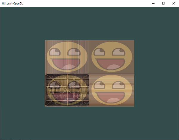
댓글 영역